Infiniti FX35, FX50 (S51). Manual — part 154

AV
DIAGNOSIS SYSTEM (AV CONTROL UNIT)
AV-389
< SYSTEM DESCRIPTION >
[NAVIGATION (TWIN MONITOR)]
C
D
E
F
G
H
I
J
K
L
M
B
A
O
P
Some error items may be displayed simultaneously according to the cause. If some error items are displayed
simultaneously, the detection of the cause can be performed by the combination of display items
Error item
Description
Possible malfunction factor/Action to take
CAN COMM CIRCUIT
CAN communication malfunction is detect-
ed.
Perform diagnosis with CONSULT-III, and
then repair the malfunctioning parts accord-
ing to the diagnosis results.
Refer to
AV-393, "CONSULT - III Function
CONTROL UNIT (CAN)
CAN initial diagnosis malfunction is detect-
ed.
Replace the AV control unit if the malfunc-
tion occurs constantly.
CONTROL UNIT (AV)
AV communication circuit initial diagnosis
malfunction is detected.
FLASH-ROM Error Of Control Unit
AV control unit malfunction is detected.
Connection Of Gyro
Connection of G Sensor
CAN Controller Memory Error
Bluetooth Module Connection Error
Sub CPU Connection Error
iPod authentification chip error
Audio connection error
DSP Connection Error
AV control unit malfunction is detected.
• If a disc can be played, then there is a
possibility of the detection of a temporary
malfunction.
• Replace the AV control unit if the mal-
function occurs constantly.
DSP Communication Error
HDD Connection Error
AV control unit malfunction is detected.
• If the music box function has no malfunc-
tions, then there is a possibility of the de-
tection of a temporary malfunction.
• Replace the AV control unit if the mal-
function occurs constantly.
HDD Read Error
HDD Write Error
HDD Communication Error
HDD Access Error
GPS Communication Error
GPS malfunction is detected.
An intermittent error caused by strong radio
interference may be detected unless any
symptom (GPS reception error, etc.) oc-
curs.
Replace the AV control unit if the malfunc-
tion occurs constantly.
GPS ROM Error
GPS RAM Error
GPS RTC Error
Unfinished configuration
The writing of configuration data is incom-
plete.
Write configuration data with CONSULT-III.
USB Controller Communication Error
USB connection malfunction is detected.
Check that the connection to the USB con-
nector is normal.
DVD Mechanism Communication Error
AV control unit malfunction is detected.
• If DVD can be played, then there is a
possibility of the detection of a temporary
malfunction.
• Replace the AV control unit if the mal-
function occurs constantly.
Steer. Angle Sensor Calibration
Predictive course line center position ad-
justment of the steering angle sensor is in-
complete.
Adjust the predictive course line center po-
sition of the steering angle sensor.
Refer to

AV-390
< SYSTEM DESCRIPTION >
[NAVIGATION (TWIN MONITOR)]
DIAGNOSIS SYSTEM (AV CONTROL UNIT)
Speaker Test
Front Display Connection Error
When either one of the following items are
detected:
• front display unit power supply and
ground circuits malfunction is detected.
• malfunction is detected in communica-
tion circuits between AV control unit and
front display unit.
• Front display unit power supply and
ground circuits.
• Communication circuits between AV con-
trol unit and front display unit.
Rear Display Connection Error
When either one of the following items are
detected:
• rear display unit power supply and
ground circuits malfunction is detected.
• malfunction is detected in communica-
tion circuits between AV control unit and
rear display unit.
• Rear display unit power supply and
ground circuits.
• Communication circuits between AV con-
trol unit and rear display unit.
GPS Antenna Error
GPS antenna connection malfunction is de-
tected.
Check the connection of the GPS antenna
connector.
XM Antenna Connection Error
Satellite radio antenna connection malfunc-
tion is detected.
Satellite radio antenna disconnection.
USB electric current Error
Detection of overcurrent in USB connector.
Check USB harness between the AV con-
trol unit and USB connector.
• AV COMM CIRCUIT
• Switches Connection Error
When either one of the following items are
detected:
• multifunction switch power supply and
ground circuits are malfunctioning.
• AV communication circuits between AV
control unit and multifunction switch are
malfunctioning.
• Multifunction switch power supply and
ground circuits.
• AV communication circuits between AV
control unit and multifunction switch.
• AV COMM CIRCUIT
• AVM Connection Error
Around view monitor control unit power
supply and ground circuits are malfunction-
ing.
Around view monitor control unit power
supply and ground circuits.
• AV COMM CIRCUIT
• AVM Sonar Connection Error
When either one of the following items are
detected:
• sonar control unit power supply and
ground circuits are malfunctioning.
• AV communication circuits between AV
control unit and sonar control unit are
malfunctioning.
• Sonar control unit power supply and
ground circuits.
• AV communication circuits between AV
control unit and sonar control unit.
• AV COMM CIRCUIT
• Video Distributor Connection Error
• Rear Display Connection Error
When either one of the following items are
detected:
• video distributor power supply and
ground circuits are malfunctioning.
• AV communication circuits between
around view monitor control unit and vid-
eo distributor are malfunctioning.
• Video distributor power supply and
ground circuits.
• AV communication circuits between
around view monitor control unit and vid-
eo distributor.
• AV COMM CIRCUIT
• Video Distributor Connection Error
• Rear Display Connection Error
• AVM Connection Error
AV communication circuits between multi-
function switch and around view monitor
control unit are malfunctioning.
AV communication circuits between multi-
function switch and around view monitor
control unit.
• AV COMM CIRCUIT
• Switches Connection Error
• Video Distributor Connection Error
• Rear Display Connection Error
• AVM Connection Error
AV communication circuits between AV
control unit and multifunction switch are
malfunctioning.
AV communication circuits between AV
control unit and multifunction switch.
Error item
Description
Possible malfunction factor/Action to take
AV
DIAGNOSIS SYSTEM (AV CONTROL UNIT)
AV-391
< SYSTEM DESCRIPTION >
[NAVIGATION (TWIN MONITOR)]
C
D
E
F
G
H
I
J
K
L
M
B
A
O
P
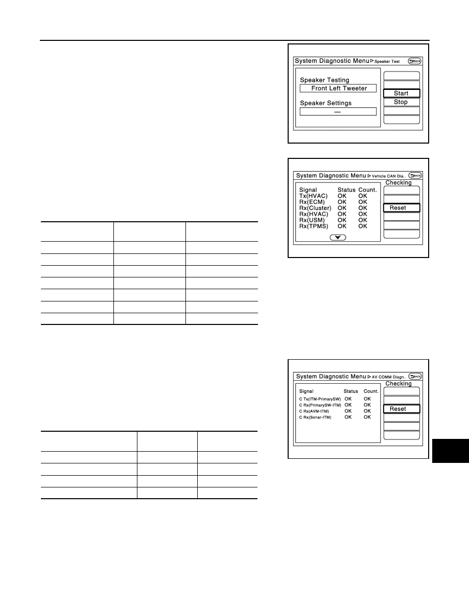
Select “SPEAKER DIAGNOSIS” to display the Speaker Diagnosis
screen. Press “Start” to generate a test tone in a speaker. Press
“Start” to generate a test tone in the next speaker. Press “Stop” to
stop the test tones.
Vehicle CAN Diagnosis
• CAN communication status and error counter is displayed.
• The error counter displays “OK” if any malfunction was not
detected in the past and displays “0” if a malfunction is detected. It
increases by 1 if the condition is normal at the next ignition switch
ON cycle. The upper limit of the counter is 39.
• The error counter is erased if “Reset” is pressed.
NOTE:
“???” indicates UNKWN.
AV COMM Diagnosis
• Displays the communication status between AV control unit (mas-
ter unit) and each unit.
• The error counter displays “OK” if any malfunction was not
detected in the past and displays “0” if a malfunction is detected. It
increases by 1 if the condition is normal at the next ignition switch
ON cycle. The upper limit of the counter is 39.
• The error counter is erased if “Reset” is pressed.
NOTE:
“???” indicates UNKWN
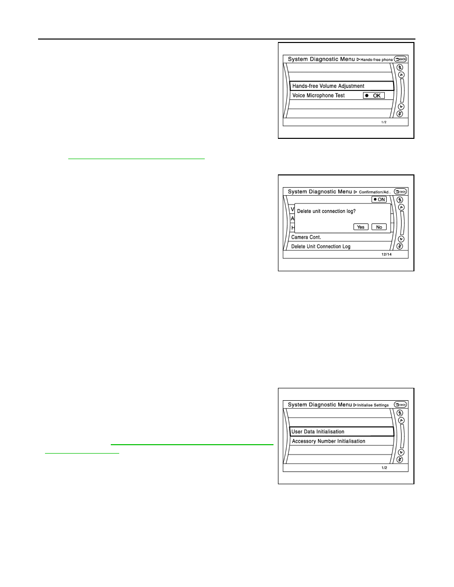
Hands-Free Phone
JPNIA1828ZZ
Items
Display (Current)
Malfunction counter
(Past)
Tx(HVAC)
OK / ???
OK / 0 – 39
Rx(ECM)
OK / ???
OK / 0 – 39
Rx(Cluster)
OK / ???
OK / 0 – 39
Rx(HVAC)
OK / ???
OK / 0 – 39
Rx(USM)
OK / ???
OK / 0 – 39
Rx(TPMS)
OK / ???
OK / 0 – 39
Rx(STRG)
OK / ???
OK / 0 – 39
JSNIA2391ZZ
Items
Status
(Current)
Counter
(Past)
C Tx(ITM–PrimarySW)
OK / ???
OK / 0 – 39
C Rx(PrimarySW–ITM)
OK / ???
OK / 0 – 39
C Rx(AVM–ITM)
OK / ???
OK / 0 – 39
C Rx(Sonar–ITM)
OK / ???
OK / 0 – 39
JSNIA2392ZZ
AV-392
< SYSTEM DESCRIPTION >
[NAVIGATION (TWIN MONITOR)]
DIAGNOSIS SYSTEM (AV CONTROL UNIT)
The hands-free phone reception volume adjustment and microphone
and speaker test functions are also available.
Camera Cont.
AV-397, "On Board Diagnosis Function"
Delete Unit Connection Log
Deletes any unit connection records and error records from the AV
control unit memory. (Clear the records of the unit that has been
removed.)
Initialize Settings
“User Data Initialization” and “Accessory Number Initialization” are
possible.
CAUTION:
• Never perform Accessory Number Initialization except when
configuration is unsuccessful.
• Accessory Number Initialization requires configuration. For
details, refer to
AV-460, "CONFIGURATION (AV CONTROL
Version Information
JSNIA2183ZZ
JSNIA2189ZZ
JSNIA2190ZZ
Нет комментариевНе стесняйтесь поделиться с нами вашим ценным мнением.
Текст