Infiniti FX35, FX50 (S51). Manual — part 153
AV
DIAGNOSIS SYSTEM (AV CONTROL UNIT)
AV-385
< SYSTEM DESCRIPTION >
[NAVIGATION (TWIN MONITOR)]
C
D
E
F
G
H
I
J
K
L
M
B
A
O
P
A Connecting Cable Between Units Is Displayed In Yellow.
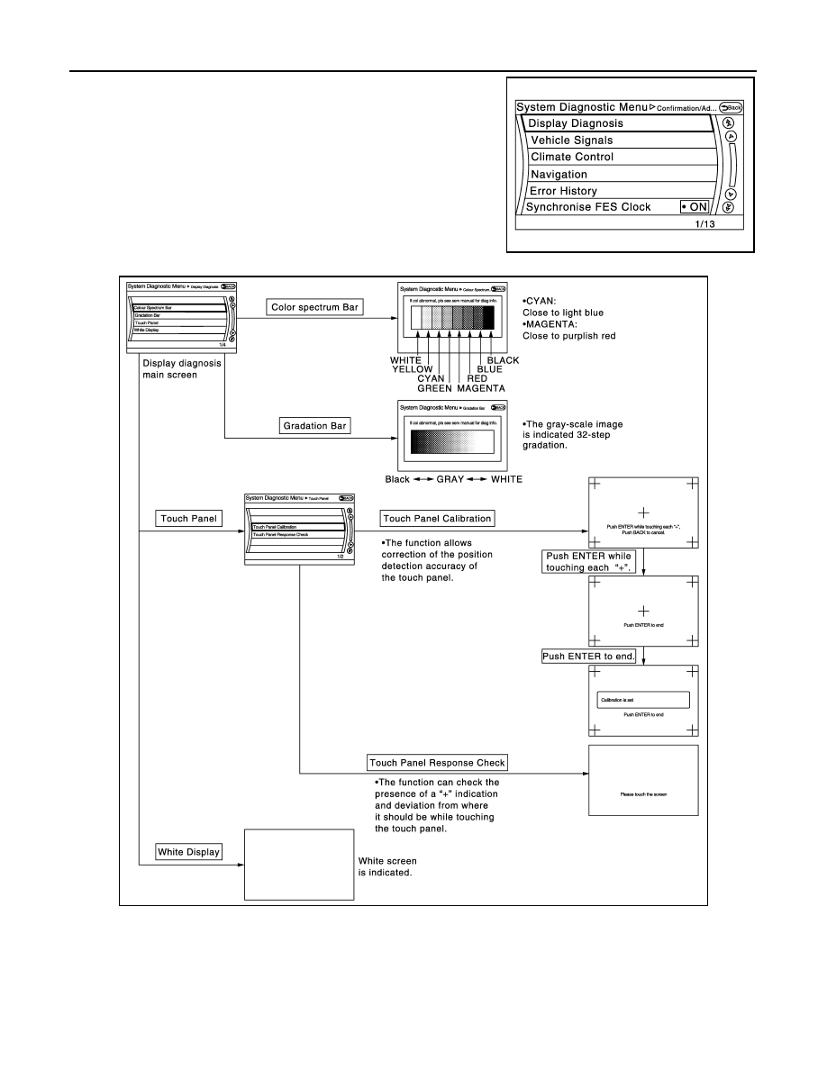
CONFIRMATION/ADJUSTMENT MODE
1.
Start the diagnosis function and select “Confirmation/Adjustment”. The confirmation/adjustment mode
indicates where each item can be checked or adjusted.
Screen switch
Description
Possible malfunction location / Action to
take
Control Unit
Malfunction is detected in AV control unit
power supply and ground circuits.
Check AV control unit power supply and
ground circuits. When detecting no mal-
function in those components, replace AV
control unit.
Rear Display
When either one of the following items are
detected:
• rear display unit power supply and
ground circuits are malfunctioning.
• serial communication circuits between
around view monitor control unit and vid-
eo distributor are malfunctioning.
• Rear display unit power supply and
ground circuits are malfunctioning.
• serial communication circuits between
around view monitor control unit and vid-
eo distributor are malfunctioning.
Area with yellow connection lines
Description
Possible malfunction location / Action to
take
Control unit
⇔
Front Display
Malfunction is detected in serial communi-
cation circuits between AV control unit and
front display unit.
Serial communication circuits between AV
control unit and front display unit.
Control unit
⇔
GPS Antenna
GPS antenna connection malfunctions de-
tected.
GPS antenna
Control unit
⇔
SAT Antenna
Satellite antenna connection malfunctions
detected.
Satellite radio antenna
Control unit
⇔
Around view
• around view monitor control unit power
supply and ground circuits are malfunc-
tioning.
Around view monitor control unit power
supply and ground circuits.
Around view
⇔
Sonar
When either one of the following items are
detected:
• sonar control unit power supply and
ground circuits are malfunctioning.
• AV communication circuits between AV
control unit and sonar control unit are
malfunctioning.
• Sonar control unit power supply and
ground circuits.
• AV communication circuits between AV
control unit and sonar control unit.
Control unit
⇔
Video Dist
When either one of the following items are
detected:
• video distributor power supply and
ground circuits are malfunctioning.
• AV communication circuits between
around view monitor control unit and vid-
eo distributor are malfunctioning.
• Video distributor power supply and
ground circuits.
• AV communication circuits between
around view monitor and video distribu-
tor.
Control unit
⇔
Around view
Control unit
⇔
Video Dist
AV communication circuits between around
view monitor control unit and multifunction
switch are malfunctioning.
AV communication circuits between around
view monitor control unit and multifunction
switch.
AV-386
< SYSTEM DESCRIPTION >
[NAVIGATION (TWIN MONITOR)]
DIAGNOSIS SYSTEM (AV CONTROL UNIT)
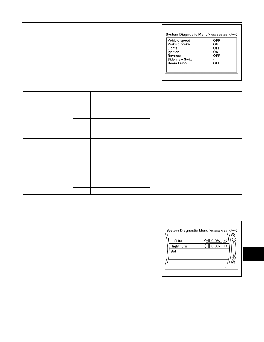
2.
Select each switch on the “Confirmation/Adjustment Mode”
screen to display the relevant trouble diagnosis screen. Press
the “Back” switch to return to the initial Confirmation/Adjustment
Mode screen.
Display Diagnosis
Vehicle Signals
JSNIA2175ZZ
JSNIA2176GB
AV
DIAGNOSIS SYSTEM (AV CONTROL UNIT)
AV-387
< SYSTEM DESCRIPTION >
[NAVIGATION (TWIN MONITOR)]
C
D
E
F
G
H
I
J
K
L
M
B
A
O
P
A comparison check can be made of each actual vehicle signal and
the signals recognized by the system.
Climate Control
Refer to “HEATER & AIR CONDITIONING CONTROL SYSTEM” for details.
Navigation
STEERING ANGLE ADJUSTMENT
The steering angle output value detected with the gyroscope is
adjusted.
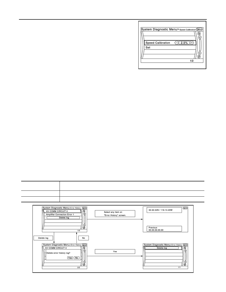
SPEED CALIBRATION
JSNIA2177ZZ
Diagnosis item
Display
Vehicle status
Remarks
Vehicle speed
ON
Vehicle speed > 0 km/h (0 MPH)
Changes in indication may be delayed. This is normal.
OFF
Vehicle speed = 0 km/h (0 MPH)
Parking brake
ON
Parking brake is applied.
OFF
Parking brake is released.
Lights
ON
Light switch ON
—
OFF
Light switch OFF
Ignition
ON
Ignition switch ON
—
OFF
Ignition switch in ACC position
Reverse
ON
Shift the selector lever to “R” posi-
tion
Changes in indication may be delayed. This is normal.
OFF
Shift the selector lever other than
“R” position
SIDE VIEW SW
—
—
This item is displayed, but cannot be monitored.
ROOM LAMP
ON
After opening any door; 5 seconds.
Check 10 seconds later, after closing all doors.
OFF
Except for above.
JSNIA2179ZZ
AV-388
< SYSTEM DESCRIPTION >
[NAVIGATION (TWIN MONITOR)]
DIAGNOSIS SYSTEM (AV CONTROL UNIT)
During normal driving, distance error caused by tire wear and tire
pressure change is automatically adjusted for by the automatic dis-
tance correction function. This function, on the other hand, is for
immediate adjustment, in cases such as driving with tire chain fitted
on tires.
Error History
The self-diagnosis results are judged depending on whether any error occurs from when “Self-diagnosis” is
selected until the self-diagnosis results are displayed.
However, the diagnosis results are judged normal if an error has occurred before the ignition switch is turned
ON and then no error has occurred until the self-diagnosis start. Check the “Error Record” to detect any error
that may have occurred before the self-diagnosis start because of this situation.
The error record displays the time and place of the most recent occurrence of that error. However, take note of
the following points.
• If there is a malfunction with the GPS antenna circuit board in the AV control unit, the correct date and time
of occurrence may not be able to be displayed.
• Place of the error occurrence is represented by the position of the current location mark at the time an error
occurred. If current location mark has deviated from the correct position, then the place of the error occur-
rence cannot be located correctly.
• The frequency of occurrence is displayed in a count up manner. The actual count up method differs depend-
ing on the error item.
Count up method A
• The counter resets to 0 if an error occurs when IGN switch is turned ON. The counter increases by 1 if the
condition is normal at a next IGN ON cycle.
• The counter upper limit is 39. Any counts exceeding 39 are ignored.“ The counter can be reset (no error
record display) with the “Delete log” switch or CONSULT-III.
Count up method B
• The counter increases by 1 if an error occurs when IGN switch is ON. The counter will not decrease even if
the condition is normal at the next IGN ON cycle.
• The counter upper limit is 50. Any counts exceeding 50 are ignored. “ The counter can be reset (no error
record display) with the “Delete log” switch or CONSULT-III.
Error item
JSNIA2180ZZ
Display type of occur-
rence frequency
Error history display item
Count up method A
CAN communication line, control unit (CAN), AV communication line, control unit (AV)
Count up method B
Other than the above
JPNIA1788GB
Нет комментариевНе стесняйтесь поделиться с нами вашим ценным мнением.
Текст