Infiniti FX35, FX50 (S51). Manual — part 1871
P1815 M-MODE SWITCH
TM-291
< DTC/CIRCUIT DIAGNOSIS >
[7AT: RE7R01B (VK50VE)]
C
E
F
G
H
I
J
K
L
M
A
B
TM
N
O
P
Diagnosis Procedure
INFOID:0000000005250299
1.
CHECK MANUAL MODE SWITCH CIRCUIT
With CONSULT-III
1.
Turn ignition switch ON.
2.
Select “MANU MODE SW”, “NON M MODE SW”, “UP SW LEVER”, “DOWN SW LEVER”, “SFT UP ST
SW”* and “SFT DWN ST SW”* in “Data Monitor” in “TRANSMISSION”.
3.
Check the ON/OFF operations of each monitor item.
*: With paddle shifter
Without CONSULT-III
Drive the vehicle in the manual mode, and then check that the indication of the shift position indicator matches
with the actual gear position.
1.
Shift the selector lever to UP side, and then accelerate from 1GR to 7GR.
2.
Shift the selector lever to DOWN side, and then decelerate from 7GR to 1GR.
3.
*Shift the paddle shifter to UP side, and then accelerate from 1GR to 7GR.
4.
*Shift the paddle shifter to DOWN side, and then decelerate from 7GR to 1GR.
*: With paddle shifter
Which item is abnormal?
Manual mode switch>>GO TO 2.
Paddle shifter>>GO TO 7.
2.
CHECK MANUAL MODE SWITCH CIRCUIT
1.
Turn ignition switch OFF.
2.
Disconnect A/T shift selector connector.
3.
Turn ignition switch ON.
4.
Check voltage between A/T shift selector vehicle side harness connector terminals.
Is the inspection result normal?
YES
>> GO TO 3.
NO
>> GO TO 4.
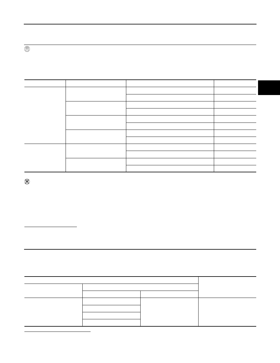
Item
Monitor Item
Condition
Status
Manual mode switch
MANU MODE SW
Manual shift gate side (neutral)
ON
Other than the above
OFF
NON M-MODE SW
Manual shift gate side
OFF
Other than the above
ON
UP SW LEVER
Selector lever: UP (+ side)
ON
Other than the above
OFF
DOWN SW LEVER
Selector lever: DOWN (
−
side)
ON
Other than the above
OFF
Paddle shifter*
SFT UP ST SW
Paddle shifter: UP (+ side)
ON
Other than the above
OFF
SFT DWN ST SW
Paddle shifter: DOWN (
−
side)
ON
Other than the above
OFF
A/T shift selector vehicle side harness connector
Voltage (Approx.)
Connector
Terminal
+
−
M137
1
4
Battery voltage
2
3
5

TM-292
< DTC/CIRCUIT DIAGNOSIS >
[7AT: RE7R01B (VK50VE)]
P1815 M-MODE SWITCH
3.
CHECK MANUAL MODE SWITCH
1.
Turn ignition switch OFF.
2.
Check manual mode switch. Refer to
TM-294, "Component Inspection (Manual Mode Switch)"
Is the inspection result normal?
YES
>> GO TO 12.
NO
>> Repair or replace damaged parts.
4.
CHECK GROUND CIRCUIT (MANUAL MODE SWITCH CIRCUIT)
1.
Turn ignition switch OFF.
2.
Check continuity between A/T shift selector vehicle side harness connector terminal and ground.
Is the inspection result normal?
YES
>> GO TO 5.
NO
>> Repair or replace damaged parts.
5.
CHECK HARNESS BETWEEN A/T SHIFT SELECTOR AND UNIFIED METER AND A/C AMP. (STEP 1)
1.
Disconnect unified meter and A/C amp. connector.
2.
Check continuity between A/T shift selector vehicle side harness connector terminals and unified meter
and A/C amp. vehicle side harness connector terminals.
Is the inspection result normal?
YES
>> GO TO 6.
NO
>> Repair or replace damaged parts.
6.
CHECK HARNESS BETWEEN A/T SHIFT SELECTOR AND UNIFIED METER AND A/C AMP. (STEP 2)
Check continuity between A/T shift selector vehicle side harness connector terminals and ground.
Is the inspection result normal?
YES
>> GO TO 12.
NO
>> Repair or replace damaged parts.
7.
CHECK PADDLE SHIFTER CIRCUIT
1.
Turn ignition switch OFF.
2.
Disconnect paddle shifter connectors.
3.
Turn ignition switch ON.
4.
Check voltage between paddle shifter vehicle side harness connector terminals.
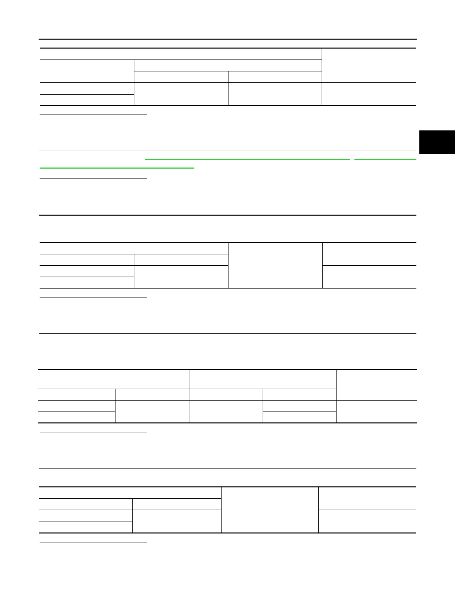
A/T shift selector vehicle side harness connector
Ground
Continuity
Connector
Terminal
M137
4
Existed
A/T shift selector vehicle side harness connector
Unified meter and A/C amp. vehicle side harness
connector
Continuity
Connector
Terminal
Connector
Terminal
M137
1
M66
10
Existed
2
25
3
5
5
11
A/T shift selector vehicle side harness connector
Ground
Continuity
Connector
Terminal
M137
1
Not existed
2
3
5
P1815 M-MODE SWITCH
TM-293
< DTC/CIRCUIT DIAGNOSIS >
[7AT: RE7R01B (VK50VE)]
C
E
F
G
H
I
J
K
L
M
A
B
TM
N
O
P
Is the inspection result normal?
YES
>> GO TO 8.
NO
>> GO TO 9.
8.
CHECK PADDLE SHIFTER
Check paddle shifter. Refer to
TM-294, "Component Inspection [Paddle Shifter (Shift-up)]"
,
nent Inspection [Paddle Shifter (Shift-down)]"
.
Is the inspection result normal?
YES
>> GO TO 12.
NO
>> Repair or replace damaged parts.
9.
CHECK GROUND CIRCUIT (PADDLE SHIFTER CIRCUIT)
1.
Turn ignition switch OFF.
2.
Check continuity between paddle shifter vehicle side harness connector terminal and ground.
Is the inspection result normal?
YES
>> GO TO 10.
NO
>> Repair or replace damaged parts.
10.
CHECK HARNESS BETWEEN PADDLE SHIFTER AND UNIFIED METER AND A/C AMP. (PART 1)
1.
Disconnect unified meter and A/C amp. connector.
2.
Check continuity between paddle shifter vehicle side harness connector terminals and unified meter and
A/C amp. vehicle side harness connector terminals.
Is the inspection result normal?
YES
>> GO TO 11.
NO
>> Repair or replace damaged parts.
11.
CHECK HARNESS BETWEEN PADDLE SHIFTER AND UNIFIED METER AND A/C AMP. (PART 2)
Check continuity between paddle shifter vehicle side harness connector terminals and ground.
Is the inspection result normal?
YES
>> GO TO 12.
NO
>> Repair or replace damaged parts.
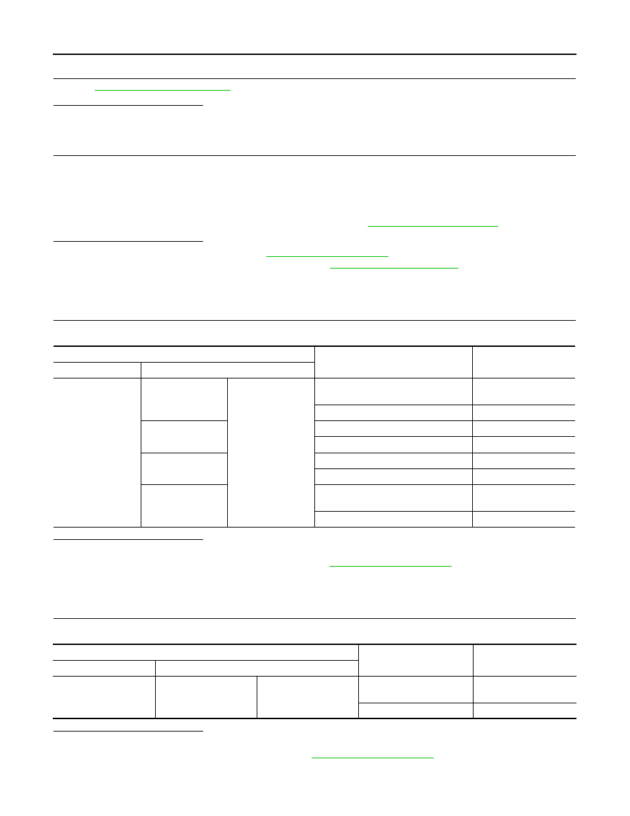
Paddle shifter vehicle side harness connector
Voltage (Approx.)
Connector
Terminal
+
−
M38
3
1
Battery voltage
M39
Paddle shifter vehicle side harness connector
Ground
Continuity
Connector
Terminal
M38
1
Existed
M39
Paddle shifter vehicle side harness connector
Unified meter and A/C amp. vehicle side harness
connector
Continuity
Connector
Terminal
Connector
Terminal
M38
3
M66
6
Existed
M39
26
Paddle shifter vehicle side harness connector
Ground
Continuity
Connector
Terminal
M38
3
Not existed
M39
TM-294
< DTC/CIRCUIT DIAGNOSIS >
[7AT: RE7R01B (VK50VE)]
P1815 M-MODE SWITCH
12.
CHECK INTERMITTENT INCIDENT
GI-36, "Intermittent Incident"
Is the inspection result normal?
YES
>> GO TO 13.
NO
>> Repair or replace damaged parts.
13.
CHECK UNIFIED METER AND A/C AMP.
1.
Reconnect all the connectors.
2.
Turn ignition switch ON.
3.
Select “M RANGE SW”, “NM RANGE SW”, “AT SFT UP SW”, “AT SFT DWN SW”, “ST SFT UP SW”* and
“ST SFT DWN SW”* on “Data Monitor” in “METER/M&A”.
*: With paddle shifter
4.
Check the ON/OFF operations of each monitor item. Refer to
.
Is the inspection result normal?
YES
>> Replace A/T assembly. Refer to
NO
>> Replace unified meter and A/C amp. Refer to
.
Component Inspection (Manual Mode Switch)
INFOID:0000000005250300
1.
CHECK MANUAL MODE SWITCH
Check continuity between A/T shift selector connector terminals.
Is the inspection result normal?
YES
>> INSPECTION END
NO
>> Replace A/T shift selector assembly. Refer to
Component Inspection [Paddle Shifter (Shift-up)]
INFOID:0000000005250301
1.
CHECK PADDLE SHIFTER (SHIFT-UP)
Check continuity between paddle shifter (shift-up) connector terminals.
Is the inspection result normal?
YES
>> INSPECTION END
NO
>> Replace paddle shifter (shift-up). Refer to
A/T shift selector connector
Condition
Continuity
Connector Terminal
M137
1
4
Selector lever is shifted to manual shift
gate side
Existed
Other than the above
Not existed
2
Selector lever is shifted to – side
Existed
Other than the above
Not existed
3
Selector lever is shifted to + side
Existed
Other than the above
Not existed
5
Selector lever is shifted to manual shift
gate side
Not existed
Other than the above
Existed
Paddle shifter (shift-up) connector
Condition
Continuity
Connector
Terminal
M38
1
3
Paddle shifter (shift-up) is
pulled.
Existed
Other than the above
Not existed
Нет комментариевНе стесняйтесь поделиться с нами вашим ценным мнением.
Текст