Infiniti FX35, FX50 (S51). Manual — part 1015

EXL-56
< DTC/CIRCUIT DIAGNOSIS >
[XENON TYPE]
B2521 ECU CIRCUIT
B2521 ECU CIRCUIT
Description
INFOID:0000000005244711
AFS control unit judges the vehicle condition from each signal. AFS control unit controls AFS function and the
headlamp aiming.
DTC Logic
INFOID:0000000005244712
DTC DETECTION LOGIC
[B2521] ECU circuit
DTC CONFIRMATION PROCEDURE
1.
DTC ERASE
Erase the DTC memory of AFS with CONSULT-III.
>> GO TO 2.
2.
DTC CONFIRMATION PROCEDURE
1.
Turn the ignition ON.
2.
Select the self-diagnosis with CONSULT-III.
3.
Check the self-diagnosis result. Refer to
Is “B2521” detected?
YES
>> Refer to
.
NO
>> Refer to
GI-36, "Intermittent Incident"
.
Diagnosis Procedure
INFOID:0000000005244713
1.
CHECK EACH SENSOR POWER SUPPLY
1.
Turn the ignition switch ON.
2.
Check the voltage between the AFS control unit harness connector and the ground.
Is the measurement value within the standard value?
YES
>> GO TO 2.
Less than the standard value >>GO TO 3.
Higher than the standard value>>GO TO 4.
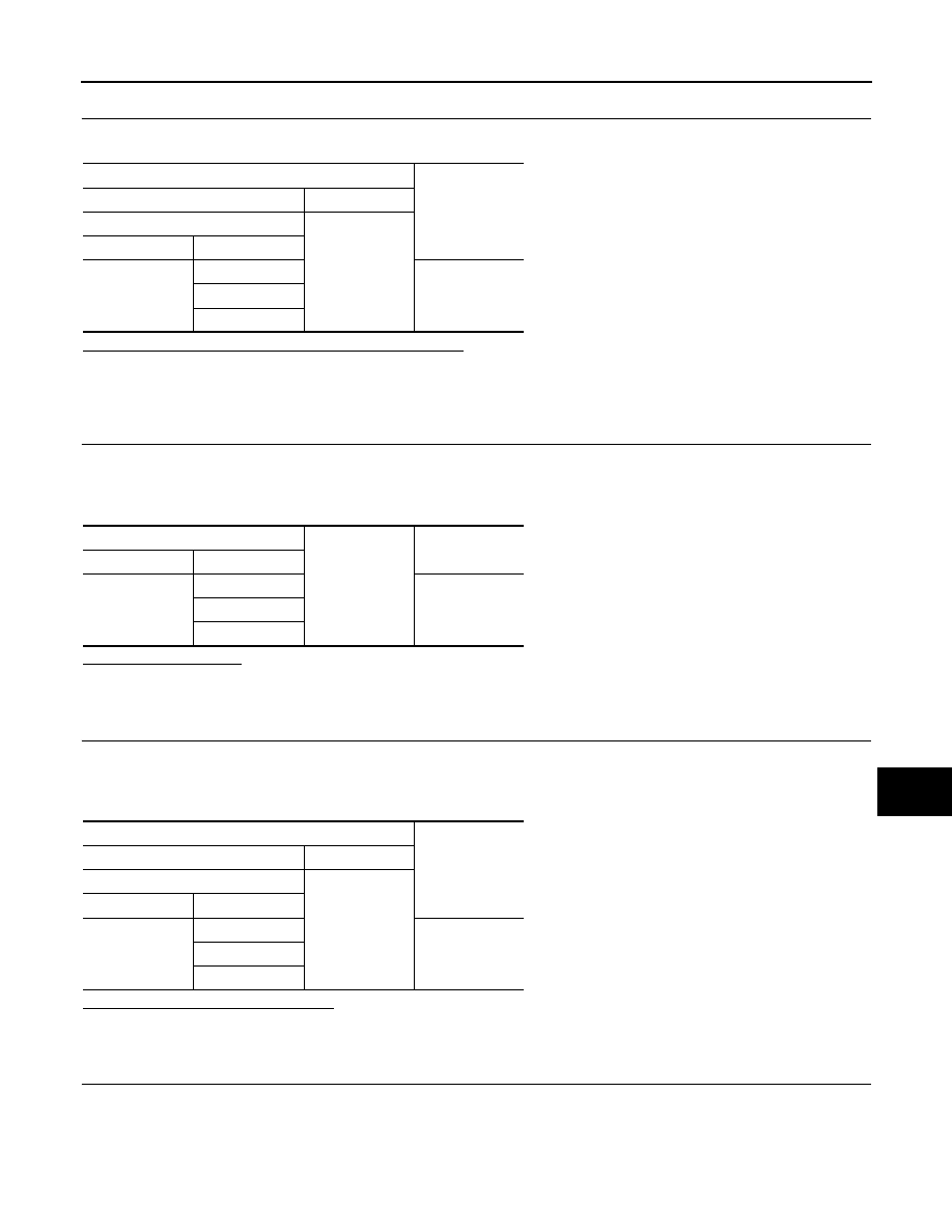
Error detection condition
DTC erase condition
Possible cause
• AFS control unit indicates an applicable DTC when de-
tecting any of the following conditions continuously for 2
seconds or more.
- The swivel position sensor is shorted to the power supply
or the ground.
- The swivel position sensor signal is shorted to the
ground.
- The height sensor power supply is shorted to the power
supply or the ground.
- The height sensor signal is shorted to the ground.
• AFS control unit RAM/ROM error
Ignition switch OFF
Swivel position sensor
• Swivel position sensor
• Harness and connector
• AFS control unit
Height sensor
• Height sensor
• Harness and connector
• AFS control unit
AFS control unit (RAM/ROM)
• AFS control unit
Terminals
Voltage
(Approx.)
(+)
(
−
)
AFS control unit
Ground
Connector
Terminal
M16
4
5 V
6
24
B2521 ECU CIRCUIT
EXL-57
< DTC/CIRCUIT DIAGNOSIS >
[XENON TYPE]
C
D
E
F
G
H
I
J
K
M
A
B
EXL
N
O
P
2.
CHECK EACH SENSOR SIGNAL
Check the voltage between the AFS control unit harness connector and the ground.
Is the measurement value within the standard value?
YES
>> Replace AFS control unit.
Less than the standard value >>GO TO 5.
Higher than the standard value>>GO TO 6.
3.
CHECK EACH SENSOR POWER SUPPLY SHORT CIRCUIT
1.
Turn the ignition switch OFF.
2.
Disconnect AFS control unit connector.
3.
Check continuity between the AFS control unit harness connector and the ground.
Does continuity exist?
YES
>> Repair the harnesses or connectors.
NO
>> Replace AFS control unit.
4.
CHECK EACH SENSOR POWER SUPPLY CIRCUIT
1.
Turn the ignition switch OFF.
2.
Disconnect AFS control unit connector.
3.
Check the voltage between the AFS control unit harness connector and the ground.
Is the measurement value normal?
YES
>> Replace AFS control unit.
NO
>> Repair the harnesses or connectors.
5.
CHECK EACH SENSOR SIGNAL SHORT CIRCUIT
1.
Turn the ignition switch OFF.
2.
Disconnect AFS control unit connector.
3.
Check continuity between the AFS control unit harness connector and the ground.
Terminals
Voltage
(Approx.)
(+)
(
−
)
AFS control unit
Ground
Connector
Terminal
M16
9
0.25 - 4.75 V
28
29
AFS control unit
Ground
Continuity
Connector
Terminal
M16
4
Not existed
6
24
Terminals
Voltage
(Approx.)
(+)
(
−
)
AFS control unit
Ground
Connector
Terminal
M16
4
0 V
6
24
EXL-58
< DTC/CIRCUIT DIAGNOSIS >
[XENON TYPE]
B2521 ECU CIRCUIT
Does continuity exist?
YES
>> Repair the harnesses or connectors.
NO
>> Replace AFS control unit.
6.
CHECK EACH SENSOR SIGNAL SHORT CIRCUIT
1.
Turn the ignition switch OFF.
2.
Disconnect AFS control unit connector.
3.
Turn the ignition switch ON.
4.
Check the voltage between the AFS control unit harness connector and the ground.
Is the measurement value normal?
YES
>> Replace AFS control unit.
NO
>> Repair the harnesses or connectors.
AFS control unit
Ground
Continuity
Connector
Terminal
M16
9
Not existed
28
29
Terminals
Voltage
(Approx.)
(+)
(
−
)
AFS control unit
Ground
Connector
Terminal
M16
9
0 V
28
29

C0126 STEERING ANGLE SENSOR SIGNAL
EXL-59
< DTC/CIRCUIT DIAGNOSIS >
[XENON TYPE]
C
D
E
F
G
H
I
J
K
M
A
B
EXL
N
O
P
C0126 STEERING ANGLE SENSOR SIGNAL
Description
INFOID:0000000005244714
AFS control unit receives the steering angle sensor signal from the steering angle sensor with CAN communi-
cation.
DTC Logic
INFOID:0000000005244715
DTC DETECTION LOGIC
[C0126] Steering angle sensor signal
DTC CONFIRMATION PROCEDURE
1.
DTC ERASE
Erase the DTC memory of AFS with CONSULT-III.
>> GO TO 2.
2.
DTC CONFIRMATION
1.
Start the engine.
2.
Turn the steering wheel to the maximum right/left.
3.
Select the self-diagnosis with CONSULT-III.
4.
Check the self-diagnosis result. Refer to
Is “C0126” detected?
YES
>> Refer to
.
NO
>> Refer to
GI-36, "Intermittent Incident"
.
Diagnosis Procedure
INFOID:0000000005244716
1.
ABS ACTUATOR AND ELECTRICAL UNIT (CONTROL UNIT) SELF-DIAGNOSIS
Check the self-diagnosis result with CONSULT-III. Check that ABS actuator and electrical unit (control unit)
does not detect any DTCs.
Is any DTC detected?
YES
>> Check ABS actuator and electrical unit (control unit).Refer to
NO
>> GO TO 2.
2.
DTC ERASE
Erase DTC memory of AFS with CONSULT-III.
Is the memory erased?
YES
>> Inspection end.
NO
>> Replace AFS control unit.
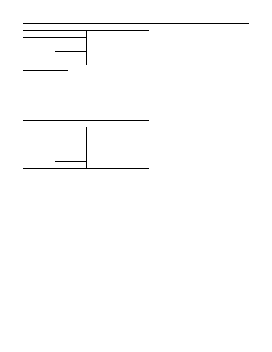
DTC detection condition
DTC erase condition
Possible causes
In any of the following conditions
• The steering angle sensor signal is not received.
• The steering angle sensor signal error is received.
• Out-of-standard signal (-900
°
- +900
°
) is received.
The ignition switch OFF
• Steering angle sensor
• AFS control unit
Нет комментариевНе стесняйтесь поделиться с нами вашим ценным мнением.
Текст