Infiniti FX35, FX50 (S51). Manual — part 311

CCS-64
< DTC/CIRCUIT DIAGNOSIS >
[ICC (FULL SPEED RANGE)]
C1A05 BRAKE SW/STOP LAMP SW
3.
Check for continuity between brake booster control unit harness connector and ground.
Is the inspection result normal?
YES
>> GO TO 12.
NO
>> Repair the harnesses or connectors.
12.
PERFORM SELF-DIAGNOSIS OF ECM
1.
Connect all connectors again if the connectors are disconnected.
2.
Turn ignition switch ON.
3.
Perform “All DTC Reading”.
4.
Check if any DTC is detected in “Self Diagnostic Result” of “ENGINE”. Refer to
(VK50VE).
Is any DTC detected?
YES
>> Repair or replace the malfunctioning parts identified by the self-diagnosis result.
NO
>> GO TO 13.
13.
CHECK ICC BRAKE HOLD RELAY DRIVE SIGNAL OUTPUT
1.
Select the active test item “STOP LAMP” of “ICC”.
2.
Check if “STP LMP DRIVE” is turned ON when operating the test item.
Is the inspection result normal?
YES
>> Replace brake booster control unit.
NO
>> Replace ICC sensor integrated unit. Refer to
Component Inspection (ICC Brake Switch)
INFOID:0000000005501592
1.
CHECK ICC BRAKE SWITCH
Check for continuity between ICC brake switch terminals.
Is the inspection result normal?
YES
>> INSPECTION END
NO
>> Replace ICC brake switch.
Component Inspection (Stop Lamp Switch)
INFOID:0000000005501593
1.
CHECK STOP LAMP SWITCH
Check for continuity between stop lamp switch terminals.
Is the inspection result normal?
Brake booster control unit
ICC brake hold relay
Continuity
Connector
Terminal
Connector
Terminal
B249
47
E91
1
Existed
Brake booster control unit
Ground
Continuity
Connector
Terminal
B249
47
Not existed
Terminal
Condition
Continuity
1
2
When brake pedal is depressed
Not exist-
ed
When brake pedal is released
Existed
Terminal
Condition
Continuity
1
2
When brake pedal is depressed
Existed
When brake pedal is released
Not exist-
ed

CCS
C1A05 BRAKE SW/STOP LAMP SW
CCS-65
< DTC/CIRCUIT DIAGNOSIS >
[ICC (FULL SPEED RANGE)]
C
D
E
F
G
H
I
J
K
L
M
B
N
P
A
YES
>> INSPECTION END
NO
>> Replace stop lamp switch.
Special Repair Requirement
INFOID:0000000005501594
DESCRIPTION
Perform the action test after adjusting the laser beam aiming of ICC sensor integrated unit when the following
operation is performed.
• Removal and installation of ICC sensor integrated unit
• Replacement of ICC sensor integrated unit
SPECIAL REPAIR REQUIREMENT
1.
LASER BEAM AIMING ADJUSTMENT OF ICC SENSOR INTEGRATED UNIT
Adjust the laser beam aiming of the ICC sensor integrated unit. Refer to
>> GO TO 2.
2.
CHECK ICC SYSTEM
1.
Erase the “Self Diagnostic Result”, and then perform “All DTC Reading” again after performing the action
test. (Refer to
CCS-18, "ACTION TEST : Description"
2.
Check that the ICC system is normal.
>> WORK END

CCS-66
< DTC/CIRCUIT DIAGNOSIS >
[ICC (FULL SPEED RANGE)]
C1A06 OPERATION SW
C1A06 OPERATION SW
Description
INFOID:0000000005501595
• Operate the ICC system ON/OFF and vehicle speed/vehicle distance setting by the ICC steering switch.
• The ICC steering switch signal is input to the ECM. It is transmitted from ECM to ICC sensor integrated unit
via CAN communication.
DTC Logic
INFOID:0000000005501596
DTC DETECTION LOGIC
NOTE:
If DTC “C1A06” is detected along with DTC “U1000”, first diagnose the DTC “U1000”. Refer to
DTC CONFIRMATION PROCEDURE
1.
PERFORM DTC CONFIRMATION PROCEDURE
1.
Start the engine.
2.
Wait for approximately 5 minutes after turning the MAIN switch of ICC system ON.
3.
Perform “All DTC Reading” with CONSULT-III.
4.
Check if the “C1A06” is detected as the current malfunction in “Self Diagnostic Result” of “ICC”.
Is “C1A06” detected as the current malfunction?
YES
>> Refer to
NO
>> Refer to
GI-36, "Intermittent Incident"
.
Diagnosis Procedure
INFOID:0000000005501597
1.
CHECK SELF-DIAGNOSIS RESULTS
Check if “U1000” is detected other than “C1A06” in “Self Diagnostic Result” of “ICC”.
Is “U1000” detected?
YES
>> Perform the CAN communication system inspection. Repair or replace the malfunctioning parts.
.
NO
>> GO TO 2.
2.
CHECK ICC STEERING SWITCH
1.
Turn the ignition switch OFF.
2.
Disconnect the ICC steering switch connector.
3.
Check the ICC steering switch. Refer to
CCS-67, "Component Inspection"
.
Is the inspection result normal?
YES
>> GO TO 3.
NO
>> Replace the ICC steering switch.
3.
CHECK HARNESS BETWEEN SPIRAL CABLE AND ECM
1.
Disconnect the ECM connector.
2.
Check for continuity between the spiral cable harness connector and ECM harness connector.
VQ35HR
DTC
(On board dis-
play)
Trouble diagnosis
name
DTC detecting condition
Possible causes
C1A06
(6)
OPERATION SW
CIRC
If the input signal from ICC steering switch is
malfunctioning
• ICC steering switch circuit
• ICC steering switch
• ECM
Spiral cable
ECM
Continuity
Connector
Terminal
Connector
Terminal
CCS
C1A06 OPERATION SW
CCS-67
< DTC/CIRCUIT DIAGNOSIS >
[ICC (FULL SPEED RANGE)]
C
D
E
F
G
H
I
J
K
L
M
B
N
P
A
VK50VE
3.
Check for continuity between spiral cable harness connector and ground.
Is the inspection result normal?
YES
>> GO TO 4.
NO
>> Repair the harnesses or connectors.
4.
CHECK SPIRAL CABLE
Check for continuity between spiral cable terminals.
Is the inspection result normal?
YES
>> GO TO 5.
NO
>> Replace the spiral cable.
5.
PERFORM SELF-DIAGNOSIS OF ECM
1.
Connect the connectors of ICC steering switch and ECM connector.
2.
Turn the ignition switch ON.
3.
Perform “All DTC Reading”.
4.
Check if any DTC is detected in “Self Diagnostic Result” of “ENGINE”.
Is any DTC detected?
YES
>> Perform self-diagnosis on the detected DTC and repair or replace the malfunctioning parts. Refer
to
(VQ35HR) or
(VK50VE).
NO
>> Replace the ICC sensor integrated unit. Refer to
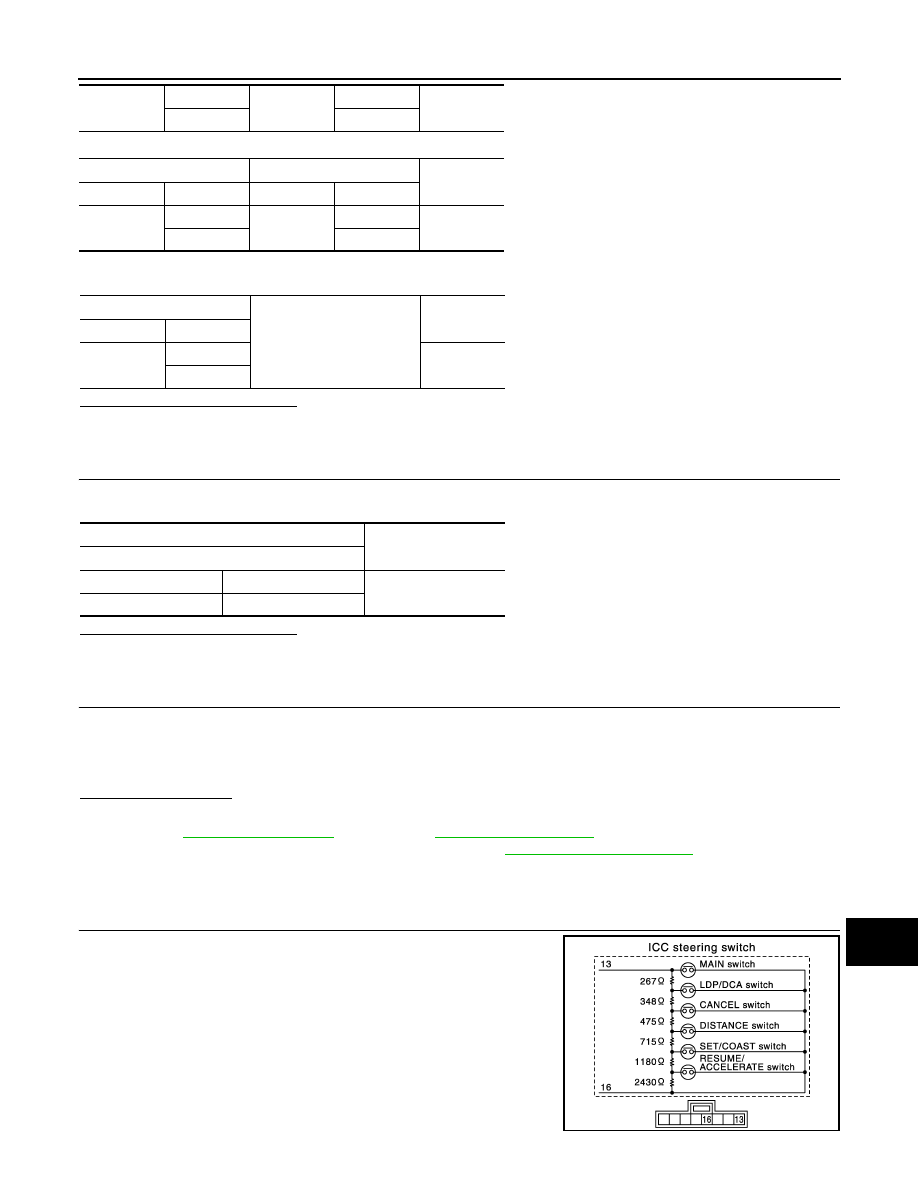
Component Inspection
INFOID:0000000005501598
1.
CHECK ICC STEERING SWITCH
Check resistance between ICC steering switch terminals.
M36
25
M107
101
Existed
32
108
Spiral cable
ECM
Continuity
Connector
Terminal
Connector
Terminal
M36
25
M160
102
Existed
32
111
Spiral cable
Ground
Continuity
Connector
Terminal
M36
25
Not existed
32
Spiral cable
Continuity
Terminal
13
25
Existed
16
32
JSOIA0141GB
Нет комментариевНе стесняйтесь поделиться с нами вашим ценным мнением.
Текст