Infiniti FX35, FX50 (S51). Manual — part 312

CCS-68
< DTC/CIRCUIT DIAGNOSIS >
[ICC (FULL SPEED RANGE)]
C1A06 OPERATION SW
Is the inspection result normal?
YES
>> INSPECTION END
NO
>> Replace the ICC steering switch.
Special Repair Requirement
INFOID:0000000005501599
DESCRIPTION
Perform the action test after adjusting the laser beam aiming of ICC sensor integrated unit when the following
operation is performed.
• Removal and installation of ICC sensor integrated unit
• Replacement of ICC sensor integrated unit
SPECIAL REPAIR REQUIREMENT
1.
LASER BEAM AIMING ADJUSTMENT OF ICC SENSOR INTEGRATED UNIT
Adjust the laser beam aiming of the ICC sensor integrated unit. Refer to
>> GO TO 2.
2.
CHECK ICC SYSTEM
1.
Erase the “Self Diagnostic Result”, and then perform “All DTC Reading” again after performing the action
test. (Refer to
CCS-18, "ACTION TEST : Description"
2.
Check that the ICC system is normal.
>> WORK END
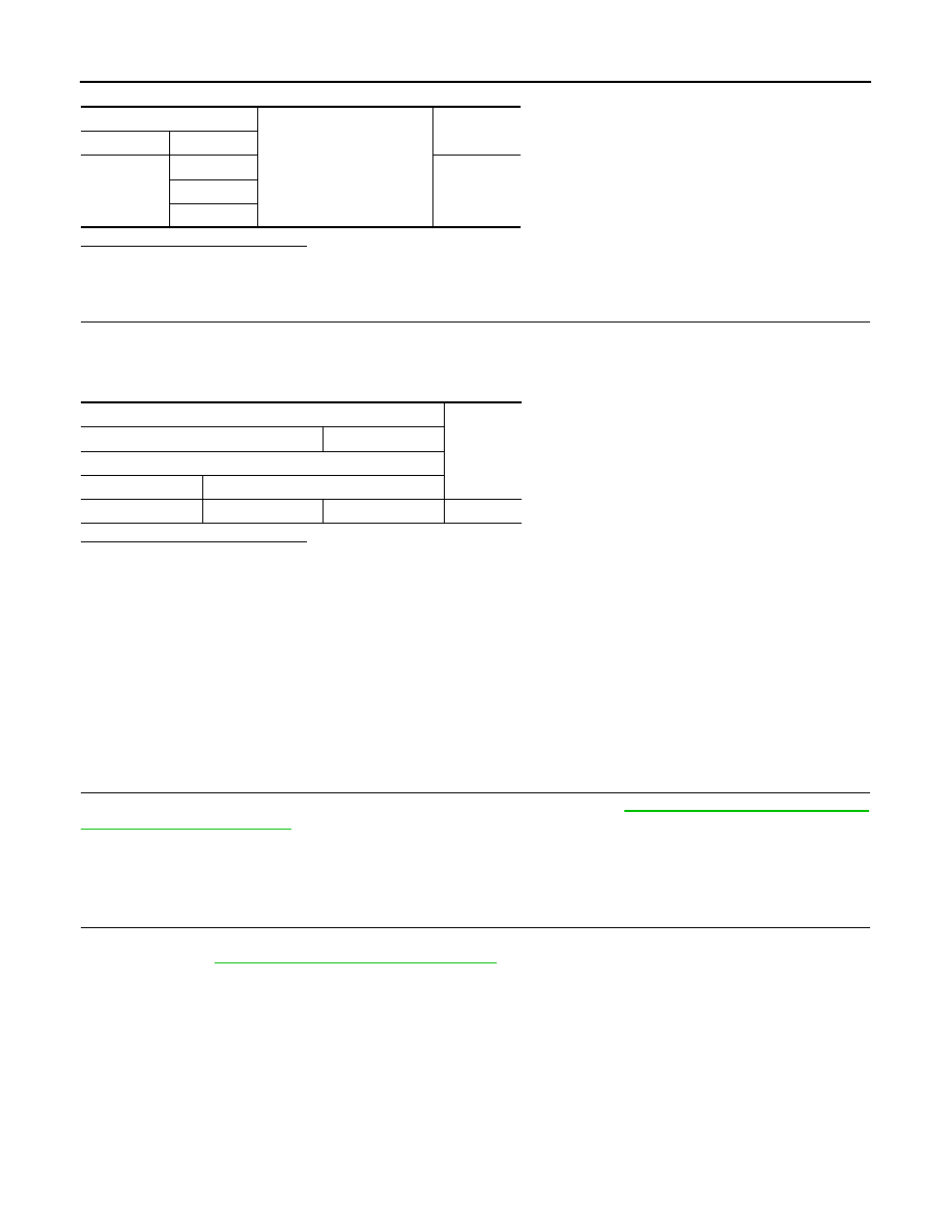
Terminal
Switch operation
Resistance
[
Ω
]
13
16
When pressing MAIN switch
Approx. 0
When pressing LDP/DCA switch
Approx. 267
When pressing CANCEL switch
Approx. 615
When pressing DISTANCE switch
Approx.
1090
When pressing SET/COAST switch
Approx.
1805
When pressing RESUME/ACCELERATE
switch
Approx.
2985
When all switches are not pressed
Approx.
5415

CCS
C1A08 PRESSURE SENSOR
CCS-69
< DTC/CIRCUIT DIAGNOSIS >
[ICC (FULL SPEED RANGE)]
C
D
E
F
G
H
I
J
K
L
M
B
N
P
A
C1A08 PRESSURE SENSOR
Description
INFOID:0000000005501600
• The brake pressure sensor detects the brake fluid pressure value in the brake master cylinder and outputs
the value to the brake booster control unit.
• The brake booster control unit receives the brake fluid pressure command signal from the ICC sensor inte-
grated unit via ITS communication and controls the brake fluid pressure while feeding back the brake fluid
pressure value (brake fluid pressure control signal).
DTC Logic
INFOID:0000000005501601
DTC DETECTION LOGIC
NOTE:
If DTC “C1A08” is detected along with DTC “U1000”, first diagnose the DTC “U1000”. Refer to
.
DTC CONFIRMATION PROCEDURE
1.
PERFORM DTC CONFIRMATION PROCEDURE
1.
Start the engine.
2.
Turn the MAIN switch of ICC system ON.
3.
Perform “All DTC Reading” with CONSULT-III.
4.
Check if the “C1A08” is detected as the current malfunction in “Self Diagnostic Result” of “ICC”.
Is “C1A08” detected as the current malfunction?
YES
>> Refer to
NO
>> Refer to
GI-36, "Intermittent Incident"
.
Diagnosis Procedure
INFOID:0000000005501602
1.
CHECK SELF-DIAGNOSIS RESULTS
Check if “U1000” is detected other than “C1A08” in “Self Diagnostic Result” of “ICC”.
Is “U1000” detected?
YES
>> Perform the CAN communication system inspection. Repair or replace the malfunctioning parts.
.
NO
>> GO TO 2.
2.
CHECK HARNESS BETWEEN BRAKE BOOSTER CONTROL UNIT AND BRAKE PRESSURE SENSOR
1.
Turn the ignition switch OFF.
2.
Disconnect connectors of brake booster control unit and brake pressure sensor.
3.
Check for continuity between the brake booster control unit harness connector and brake pressure sensor
harness connector.
4.
Check for continuity between brake booster control unit harness connector and ground.
DTC
(On board
display)
Trouble diagnosis name
DTC detecting condition
Possible causes
C1A08
(8)
PRESS SEN CIRCUIT
If the brake pressure sensor value that is input
to the brake booster control unit is malfunc-
tioning
• Brake pressure sensor circuit
• Brake pressure sensor
• Brake booster control unit
Brake booster control unit
Brake pressure sensor
Continuity
Connector
Terminal
Connector
Terminal
B250
8
E45
3
Existed
17
2
24
1
CCS-70
< DTC/CIRCUIT DIAGNOSIS >
[ICC (FULL SPEED RANGE)]
C1A08 PRESSURE SENSOR
Is the inspection result normal?
YES
>> GO TO 3.
NO
>> Repair the harnesses or connectors.
3.
CHECK BRAKE PRESSURE SENSOR POWER SUPPLY CIRCUIT
1.
Connect connectors of brake booster control unit and brake pressure sensor.
2.
Turn the ignition switch ON.
3.
Check voltage between brake booster control unit harness connectors.
Is the inspection result normal?
YES
>> Replace the brake pressure sensor.
NO
>> Replace the brake booster control unit.
Special Repair Requirement
INFOID:0000000005501603
DESCRIPTION
Perform the action test after adjusting the laser beam aiming of ICC sensor integrated unit when the following
operation is performed.
• Removal and installation of ICC sensor integrated unit
• Replacement of ICC sensor integrated unit
SPECIAL REPAIR REQUIREMENT
1.
LASER BEAM AIMING ADJUSTMENT OF ICC SENSOR INTEGRATED UNIT
Adjust the laser beam aiming of the ICC sensor integrated unit. Refer to
>> GO TO 2.
2.
CHECK ICC SYSTEM
1.
Erase the “Self Diagnostic Result”, and then perform “All DTC Reading” again after performing the action
test. (Refer to
CCS-18, "ACTION TEST : Description"
2.
Check that the ICC system is normal.
>> WORK END
Brake booster control unit
Ground
Continuity
Connector
Terminal
B250
8
Not existed
17
24
Terminals
Voltage
(Approx.)
(+)
(–)
Brake booster control unit
Connector
Terminal
B250
8
24
5 V

CCS
C1A09 BOOSTER SOLENOID
CCS-71
< DTC/CIRCUIT DIAGNOSIS >
[ICC (FULL SPEED RANGE)]
C
D
E
F
G
H
I
J
K
L
M
B
N
P
A
C1A09 BOOSTER SOLENOID
Description
INFOID:0000000005501604
• The booster solenoid is integrated with the brake booster.
• The brake booster control unit activates the booster solenoid to operate the brake booster (brake) according
to the brake fluid pressure command signal received from ICC sensor integrated unit via ITS communica-
tion.
DTC Logic
INFOID:0000000005501605
DTC DETECTION LOGIC
NOTE:
If DTC “C1A09” is detected along with DTC “U1000”, first diagnose the DTC “U1000”. Refer to
.
DTC CONFIRMATION PROCEDURE
1.
PERFORM DTC CONFIRMATION PROCEDURE
1.
Start the engine.
2.
Perform the active test item “BOOSTER SOL/V” with CONSULT-III.
3.
Perform “All DTC Reading”.
4.
Check if the “C1A09” is detected as the current malfunction in “Self Diagnostic Result” of “ICC”.
Is “C1A09” detected as the current malfunction?
YES
>> Refer to
NO
>> Refer to
GI-36, "Intermittent Incident"
.
Diagnosis Procedure
INFOID:0000000005501606
1.
CHECK SELF-DIAGNOSIS RESULTS
Check if “U1000” is detected other than “C1A09” in “Self Diagnostic Result” of “ICC”.
Is “U1000” detected?
YES
>> Perform the CAN communication system inspection. Repair or replace the malfunctioning parts.
.
NO
>> GO TO 2.
2.
CHECK BRAKE BOOSTER CONTROL UNIT POWER SUPPLY CIRCUIT
Check power supply and ground circuit of brake booster control unit. Refer to
CONTROL UNIT : Diagnosis Procedure"
.
Is the inspection result normal?
YES
>> GO TO 3.
NO
>> Repair or replace the malfunctioning parts.
3.
CHECK HARNESS BETWEEN BRAKE BOOSTER (BOOSTER SOLENOID) AND BRAKE BOOSTER
CONTROL UNIT
1.
Turn the ignition switch OFF.
2.
Disconnect connectors of brake booster control unit and brake booster.
3.
Check for continuity between the brake booster control unit harness connector and brake booster harness
connector.
DTC
(On board
display)
Trouble diagnosis name
DTC detecting condition
Possible causes
C1A09
(9)
BOOSTER SOL/V CIRC
If the booster solenoid is malfunctioning
• Booster solenoid
• Booster solenoid circuit
• Brake booster control unit
Нет комментариевНе стесняйтесь поделиться с нами вашим ценным мнением.
Текст