Infiniti FX35, FX50 (S51). Manual — part 661

P0116 ECT SENSOR
EC-185
< DTC/CIRCUIT DIAGNOSIS >
[VQ35HR]
C
D
E
F
G
H
I
J
K
L
M
A
EC
N
P
O
4.
Check resistance between “fuel level sensor unit and fuel pump (main)” terminals 4 and 5.
5.
Soak the vehicle until the resistance between “fuel level sensor unit and fuel pump (main)” terminals 4 and
5 becomes 0.5 k
Ω
higher than the value measured before soaking.
CAUTION:
Never turn ignition switch ON during soaking.
NOTE:
Soak time changes depending on ambient air temperature. It may take several hours.
6.
Start engine and let it idle for 20 minutes.
7.
Check 1st trip DTC.
Is 1st trip DTC detected?
YES
>> Go to
NO
>> INSPECTION END
Diagnosis Procedure
INFOID:0000000005236784
1.
CHECK GROUND CONNECTIONS
1.
Turn ignition switch OFF.
2.
Check ground connection M95. Refer to Ground Inspection in
Is the inspection result normal?
OK
>> GO TO 2.
NG
>> Repair or replace ground connections.
2.
CHECK ENGINE COOLANT TEMPERATURE SENSOR
EC-185, "Component Inspection"
Is the inspection result normal?
OK
>> GO TO 3.
NG
>> Replace engine coolant temperature sensor.
3.
CHECK INTERMITTENT INCIDENT
GI-36, "Intermittent Incident"
.
>> INSPECTION END
Component Inspection
INFOID:0000000005236785
1.
CHECK ENGINE COOLANT TEMPERATURE SENSOR
1.
Turn ignition switch OFF.
2.
Disconnect engine coolant temperature sensor harness connector.
3.
Remove engine coolant temperature sensor.
4.
Check resistance between engine coolant temperature sensor
terminals by heating with hot water as shown in the figure.
Is the inspection result normal?
YES
>> INSPECTION END
NO
>> Replace engine coolant temperature sensor.
Terminals
Condition
Resistance (k
Ω
)
1 and 2
Temperature [
°
C (
°
F)]
20 (68)
2.37 - 2.63
50 (122)
0.68 - 1.00
90 (194)
0.236 - 0.260
JMBIA0080ZZ
EC-186
< DTC/CIRCUIT DIAGNOSIS >
[VQ35HR]
P0117, P0118 ECT SENSOR
P0117, P0118 ECT SENSOR
Description
INFOID:0000000005236786
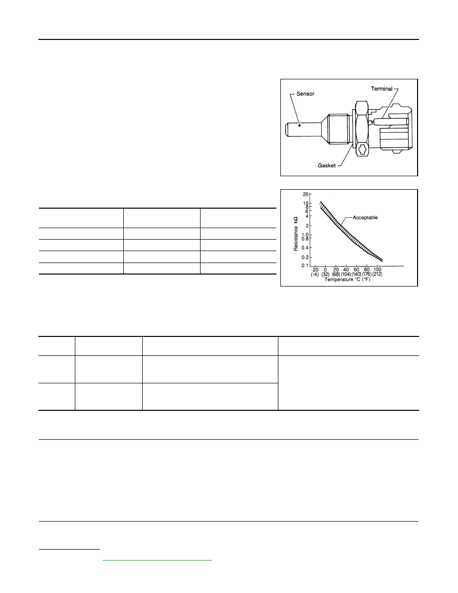
The engine coolant temperature sensor is used to detect the engine
coolant temperature. The sensor modifies a voltage signal from the
ECM. The modified signal returns to the ECM as the engine coolant
temperature input. The sensor uses a thermistor which is sensitive to
the change in temperature. The electrical resistance of the ther-
mistor decreases as temperature increases.
<Reference data>
*: These data are reference values and are measured between ECM terminals 71
(Engine coolant temperature sensor) and 84 (Sensor ground).
DTC Logic
INFOID:0000000005236787
DTC DETECTION LOGIC
DTC CONFIRMATION PROCEDURE
1.
PRECONDITIONING
If DTC Confirmation Procedure has been previously conducted, always perform the following procedure
before conducting the next test.
1.
Turn ignition switch OFF and wait at least 10 seconds.
2.
Turn ignition switch ON.
3.
Turn ignition switch OFF and wait at least 10 seconds.
>> GO TO 2.
2.
PERFORM DTC CONFIRMATION PROCEDURE
1.
Turn ignition switch ON and wait at least 5 seconds.
2.
Check DTC.
Is DTC detected?
YES
>> Go to
NO
>> INSPECTION END
SEF594K
Engine coolant temperature
[
°
C (
°
F)]
Voltage*
(V)
Resistance
(k
Ω
)
–10 (14)
4.4
7.0 - 11.4
20 (68)
3.5
2.37 - 2.63
50 (122)
2.2
0.68 - 1.00
90 (194)
0.9
0.236 - 0.260
SEF012P
DTC No.
Trouble diagnosis
name
DTC detecting condition
Possible cause
P0117
Engine coolant tem-
perature sensor cir-
cuit low input
An excessively low voltage from the sensor is
sent to ECM.
• Harness or connectors
(The sensor circuit is open or shorted.)
• Engine coolant temperature sensor
P0118
Engine coolant tem-
perature sensor cir-
cuit high input
An excessively high voltage from the sensor is
sent to ECM.

P0117, P0118 ECT SENSOR
EC-187
< DTC/CIRCUIT DIAGNOSIS >
[VQ35HR]
C
D
E
F
G
H
I
J
K
L
M
A
EC
N
P
O
Diagnosis Procedure
INFOID:0000000005236788
1.
CHECK GROUND CONNECTION
1.
Turn ignition switch OFF.
2.
Check ground connection M95. Refer to Ground Inspection in
Is the inspection result normal?
YES
>> GO TO 2.
NO
>> Repair or replace ground connection.
2.
CHECK ENGINE COOLANT TEMPERATURE (ECT) SENSOR POWER SUPPLY CIRCUIT
1.
Disconnect ECT sensor harness connector.
2.
Turn ignition switch ON.
3.
Check the voltage between ECT sensor harness connector and ground.
Is the inspection result normal?
YES
>> GO TO 4.
NO
>> GO TO 3.
3.
DETECT MALFUNCTIONING PART
Check the following.
• Harness connectors F106, F107
• Harness for open or short between ECT sensor and ECM
>> Repair open circuit, short to ground or short to power in harness or connectors.
4.
CHECK ECT SENSOR GROUND CIRCUIT FOR OPEN AND SHORT
1.
Turn ignition switch OFF.
2.
Disconnect ECM harness connector.
3.
Check the continuity between ECT sensor harness connector and ECM harness connector.
4.
Also check harness for short to ground and short to power.
Is the inspection result normal?
YES
>> GO TO 5.
NO
>> Repair open circuit, short to ground or short to power in harness or connectors.
5.
CHECK ECT SENSOR
EC-188, "Component Inspection"
Is the inspection result normal?
YES
>> GO TO 6.
NO
>> Replace ECT sensor.
6.
CHECK INTERMITTENT INCIDENT
GI-36, "Intermittent Incident"
.
>> INSPECTION END
ECT sensor
Ground
Voltage (V)
Connector
Terminal
F17
1
Ground
Approx. 5
ECT sensor
ECM
Continuity
Connector
Terminal
Connector
Terminal
F17
2
F102
84
Existed
EC-188
< DTC/CIRCUIT DIAGNOSIS >
[VQ35HR]
P0117, P0118 ECT SENSOR
Component Inspection
INFOID:0000000005236789
1.
CHECK ENGINE COOLANT TEMPERATURE SENSOR
1.
Turn ignition switch OFF.
2.
Disconnect engine coolant temperature sensor harness connector.
3.
Remove engine coolant temperature sensor.
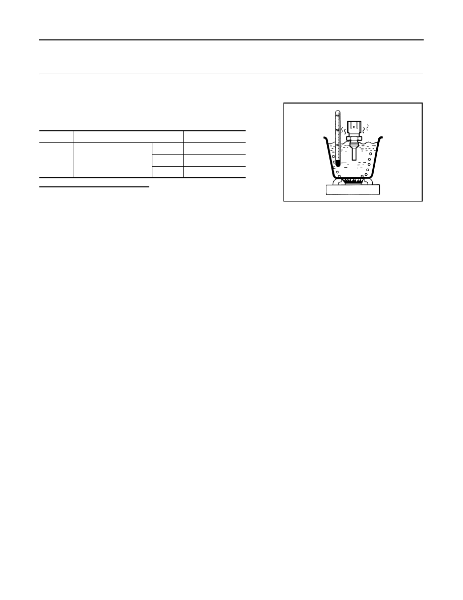
4.
Check resistance between engine coolant temperature sensor
terminals by heating with hot water as shown in the figure.
Is the inspection result normal?
YES
>> INSPECTION END
NO
>> Replace engine coolant temperature sensor.
Terminals
Condition
Resistance (k
Ω
)
1 and 2
Temperature [
°
C (
°
F)]
20 (68)
2.37 - 2.63
50 (122)
0.68 - 1.00
90 (194)
0.236 - 0.260
JMBIA0080ZZ
Нет комментариевНе стесняйтесь поделиться с нами вашим ценным мнением.
Текст