Infiniti FX35, FX50 (S51). Manual — part 975
EM-200
< UNIT REMOVAL AND INSTALLATION >
[VK50VE]
ENGINE ASSEMBLY
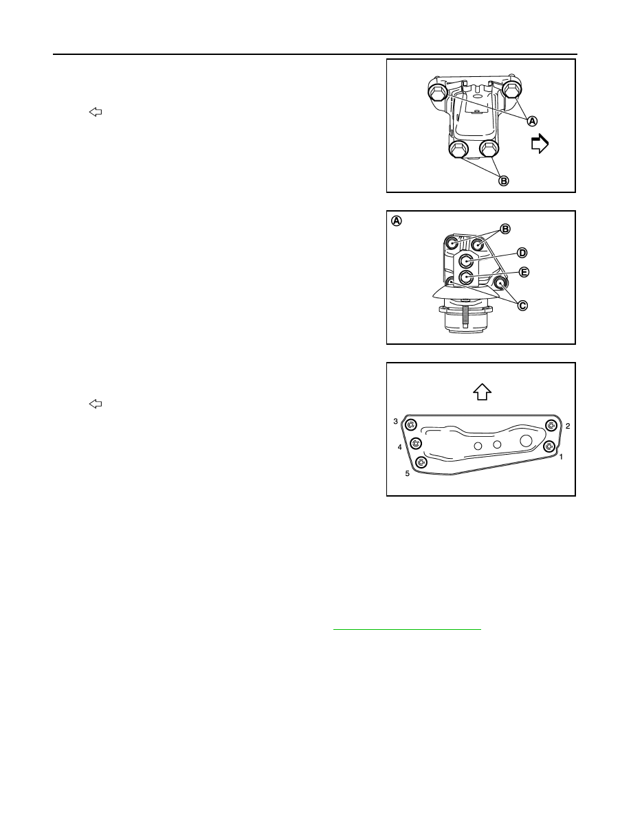
• When installing engine mounting bracket (RH and LH) on cylinder
block, tighten two upper bolts (A) first. Then tighten two lower bolts
(B).
NOTE:
This figure shows an example of bank 2.
• When installing engine mounting bracket (rear) on transfer, tighten
two upper bolts (B) first. Then tighten two lower bolts (C).
• When installing engine mounting insulator (rear) on engine mount-
ing bracket (rear), tighten upper bolts (D) first. Then tighten lower
bolts (E).
• Tighten rear engine mounting member bolts in numerical order as
shown in the figure.
• Check that all engine mounting insulators are seated properly, then tighten mounting nuts and bolts.
Inspection
INFOID:0000000005245240
INSPECTION AFTER INSTALLATION
Inspection for Leakage
The following are procedures for checking fluid leakage, lubricant leakage.
• Before starting engine, check oil/fluid levels including engine coolant and engine oil. If any are less than the
required quantity, fill them to the specified level. Refer to
MA-12, "Fluids and Lubricants"
.
• Follow the procedure below to check for fuel leakage.
- Turn ignition switch to the “ON” position (with engine stopped). With fuel pressure applied to fuel piping,
check for fuel leakage at connection points.
- Start engine. With engine speed increased, check again for fuel leakage at connection points.
• Run engine to check for unusual noise and vibration.
NOTE:
If hydraulic pressure inside chain tensioner drops after removal/installation, slack in guide may generate a
pounding noise during and just after the engine start. However, this does not indicate a malfunction. The
noise will stop after hydraulic pressure rises.
• Warm up engine thoroughly to check that there is no leakage of fuel, or any oil/fluids including engine oil and
engine coolant.
• Bleed air from lines and hoses of applicable lines, such as in cooling system.
: Engine front
JPBIA2096ZZ
A
: Rear view
JPBIA2464ZZ
: Vehicle front
JPBIA2463ZZ
ENGINE ASSEMBLY
EM-201
< UNIT REMOVAL AND INSTALLATION >
[VK50VE]
C
D
E
F
G
H
I
J
K
L
M
A
EM
N
P
O
• After cooling down engine, again check oil/fluid levels including engine oil and engine coolant. Refill them to
the specified level, if necessary.
Summary of the inspection items:
* Transmission/transaxle/CVT fluid, power steering fluid, brake fluid, etc.
Items
Before starting engine
Engine running
After engine stopped
Engine coolant
Level
Leakage
Level
Engine oil
Level
Leakage
Level
Other oils and fluids*
Level
Leakage
Level
Fuel
Leakage
Leakage
Leakage
EM-202
< UNIT DISASSEMBLY AND ASSEMBLY >
[VK50VE]
ENGINE STAND SETTING
UNIT DISASSEMBLY AND ASSEMBLY
ENGINE STAND SETTING
Setting
INFOID:0000000005245241
NOTE:
Explained here is how to disassemble with engine stand supporting transmission surface. When using a differ-
ent type of engine stand, note the difference in the steps, etc.
1.
Remove the engine assembly from the vehicle. Refer to
.
2.
Remove crankshaft pulley. Refer to
EM-194, "FRONT OIL SEAL : Removal and Installation"
.
NOTE:
The drive plate is fixed with a ring gear stopper [SST: KV10119200 (J-49277)]. Loosen the crankshaft pul-
ley mounting bolts before installing the engine stand.
3.
Remove the parts that may restrict installation of engine to a widely used engine stand.
• Fix crankshaft with a ring gear stopper [SST: KV10119200 (J-49277)]. Loosen drive plate mounting bolt
with power tool.
• Check for deformation or damage of drive plate. Refer to
.
NOTE:
The procedure is described assuming that you use a widely used engine stand holding the surface, to
which transmission is installed.
4.
Remove pilot converter using the pilot bushing puller (commercial service tool), if necessary.
5.
Lift the engine with hoist to install it onto the widely used engine stand.
CAUTION:
Use an engine stand that has a load capacity [240 kg (529 lb) or more] large enough for supporting
the engine weight.
• If the load capacity of the stand is not adequate, remove the following parts beforehand to reduce the
potential risk of overturning the stand.
- Remove intake manifold. Refer to
.
- Remove fuel injector and fuel tube assembly. Refer to
- Remove ignition coil. Refer to
- Remove rocker cover. Refer to
.
- Remove exhaust manifold. Refer to
- Other removable brackets.
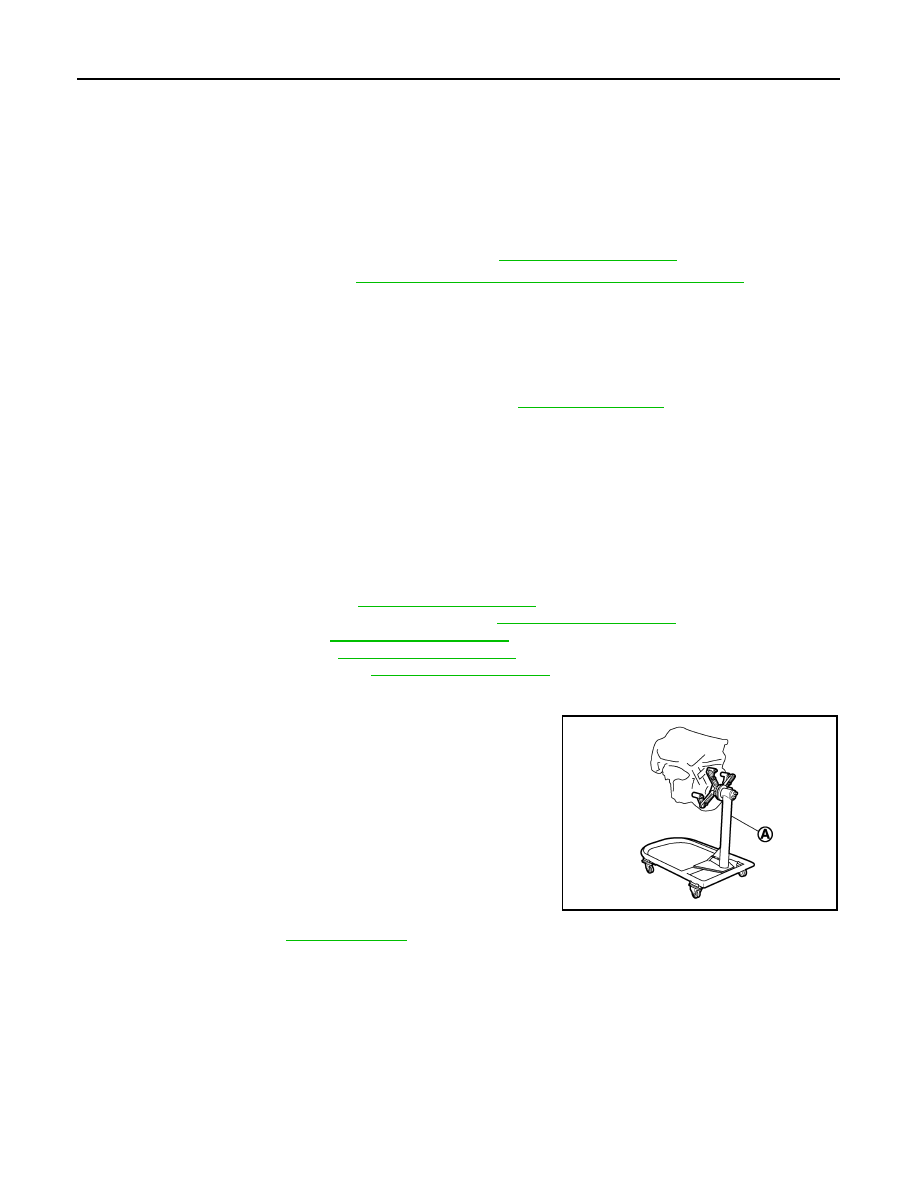
NOTE:
The figure shows an example of widely used engine stand (A)
that can hold mating surface of transmission with drive plate
removed.
CAUTION:
Before removing the hanging chains, check the engine
stand is stable and there is no risk of overturning.
6.
Drain engine oil. Refer to
.
JPBIA0190ZZ
ENGINE STAND SETTING
EM-203
< UNIT DISASSEMBLY AND ASSEMBLY >
[VK50VE]
C
D
E
F
G
H
I
J
K
L
M
A
EM
N
P
O
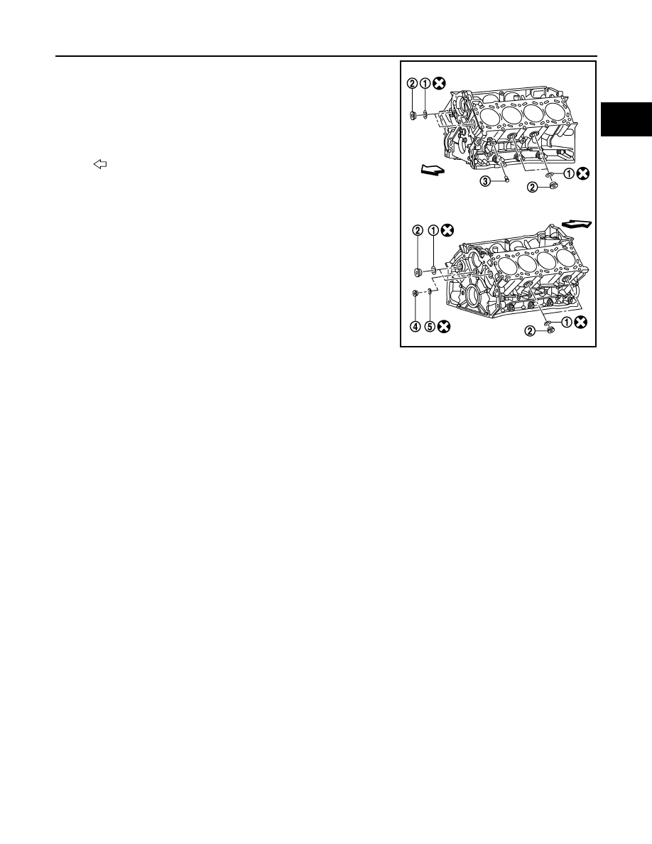
7.
Drain engine coolant by removing water drain plug (3) from both
sides of the cylinder block as shown in the figure.
1
: Washer
2
: Plug
4
: Plug
5
: Washer
: Engine front
JPBIA2121ZZ
Нет комментариевНе стесняйтесь поделиться с нами вашим ценным мнением.
Текст