Infiniti FX35, FX50 (S51). Manual — part 988
EM-252
< UNIT DISASSEMBLY AND ASSEMBLY >
[VK50VE]
CYLINDER HEAD
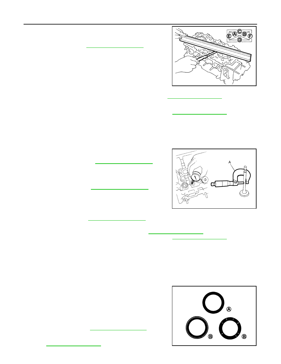
2.
At each of several locations on bottom surface of cylinder head,
measure the distortion in six directions (A, B, C, D, E, F).
• If it exceeds the limit, replace VVEL ladder assembly & cylinder
head assembly.
NOTE:
Cylinder head assembly cannot be replaced as a single part,
because it is machined together with VVEL ladder assembly.
Valve Dimensions
• Check the dimensions of each valve. For the dimensions, refer to
.
• If dimensions are out of the standard.
- Replace valve (EXH) and check valve seat contact. Refer to "VALVE SEAT CONTACT". (Exhaust side)
- Replace VVEL ladder assembly & cylinder head assembly. Refer to
. (Intake side)
NOTE:
Since the valve (INT) cannot be replaced by the piece, VVEL ladder assembly & cylinder head assembly
replacement are required.
Valve Guide Clearance
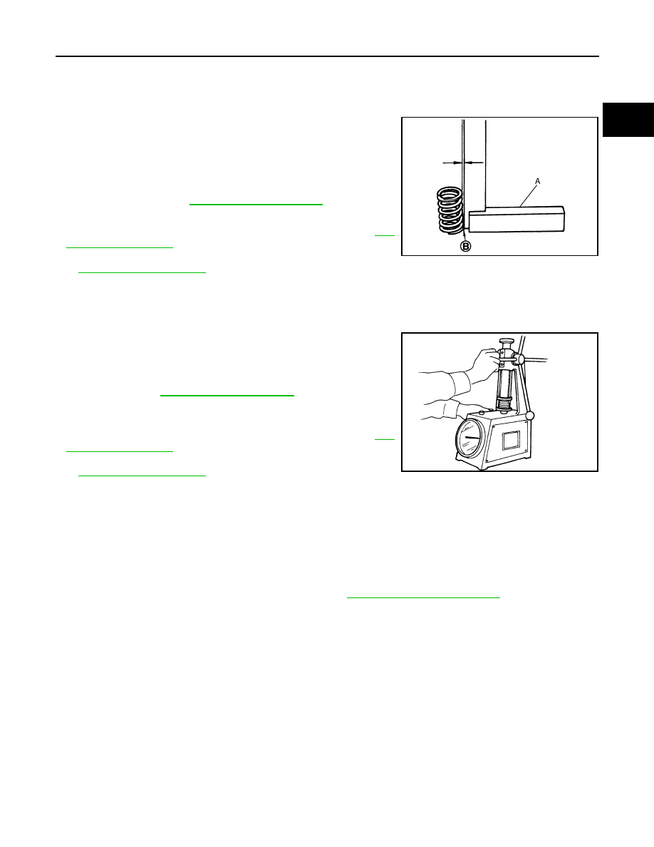
Valve Stem Diameter
• Measure the diameter of valve stem with micrometer (A).
Valve Guide Inner Diameter
• Measure the inner diameter of valve guide with bore gauge.
Valve Guide Clearance
• (Valve guide clearance) = (Valve guide inner diameter) – (Valve
stem diameter)
• If the calculated value exceeds the limit.
- Replace valve (EXH) and/or valve guide (EXH). Refer to
- Replace VVEL ladder assembly & cylinder head assembly. Refer to
. (Intake side)
NOTE:
Since the valve (INT) and valve guide (INT) cannot be replaced by the piece, VVEL ladder assembly & cylin-
der head assembly replacement are required.
Valve Seat Contact
• After confirming that the dimensions of valve guides and valves are within the specifications, perform this
procedure.
• Apply prussian blue (or white lead) onto contacting surface of valve seat to check the condition of the valve
contact on the surface.
• Check if the contact area band is continuous all around the circum-
ference.
- If not, grind to adjust valve fitting and check again. If the contacting
surface still has “NG” conditions even after the re-check, replace
valve seat (EXH). Refer to
side)
- If not, replace VVEL ladder assembly & cylinder head assembly.
. (Intake side)
Limit
: Refer to
.
JPBIA0176ZZ
Standard :
Standard
: Refer to
.
Standard
: Refer to
JPBIA0183ZZ
A
: OK
B
: NG
JPBIA0187ZZ
CYLINDER HEAD
EM-253
< UNIT DISASSEMBLY AND ASSEMBLY >
[VK50VE]
C
D
E
F
G
H
I
J
K
L
M
A
EM
N
P
O
NOTE:
Since the valve seat (INT) cannot be replaced by the piece, VVEL ladder assembly & cylinder head assem-
bly replacement are required.
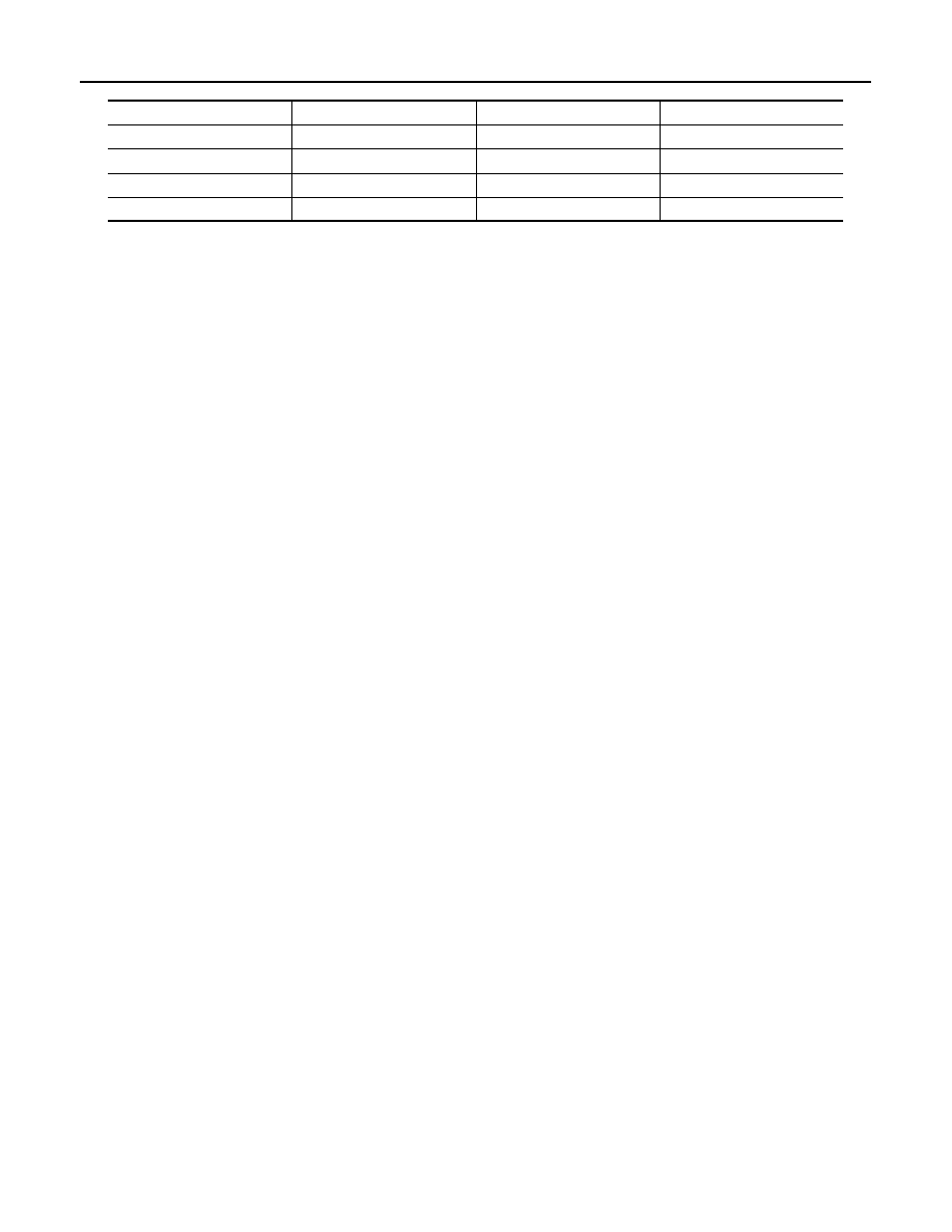
Valve Spring (with valve spring seat) Squareness
• Set a try square (A) along the side of valve spring (with valve
spring seat) and rotate spring. Measure the maximum clearance
between the top of spring and try square.
• If it exceeds the limit.
- Replace valve spring (with valve spring seat) (EXH). Refer to
- Replace VVEL ladder assembly & cylinder head assembly. Refer
. (Intake side)
NOTE:
Since the valve spring (with valve spring seat) (INT) cannot be replaced by the piece, VVEL ladder assembly
& cylinder head assembly replacement are required.
Valve Spring Dimensions and Valve Spring Pressure Load
• Check the valve spring (with valve spring seat) pressure at speci-
fied spring height.
• If the installation load or load with valve open is out of the stan-
dard.
- Replace valve spring (with valve spring seat) (EXH). Refer to
- Replace VVEL ladder assembly & cylinder head assembly. Refer
. (Intake side)
NOTE:
Since the valve spring (with valve spring seat) (INT) cannot be replaced by the piece, VVEL ladder assembly
& cylinder head assembly replacement are required.
INSPECTION AFTER ASSEMBLY
Inspection for Leakage
The following are procedures for checking fluid leakage, lubricant leakage.
• Before starting engine, check oil/fluid levels including engine coolant and engine oil. If any are less than the
required quantity, fill them to the specified level. Refer to
MA-12, "Fluids and Lubricants"
.
• Follow the procedure below to check for fuel leakage.
- Turn ignition switch to the “ON” position (with engine stopped). With fuel pressure applied to fuel piping,
check for fuel leakage at connection points.
- Start engine. With engine speed increased, check again for fuel leakage at connection points.
• Run engine to check for unusual noise and vibration.
NOTE:
If hydraulic pressure inside chain tensioner drops after removal/installation, slack in guide may generate a
pounding noise during and just after the engine start. However, this does not indicate a malfunction. The
noise will stop after hydraulic pressure rises.
• Warm up engine thoroughly to check that there is no leakage of fuel, or any oil/fluids including engine oil and
engine coolant.
• Bleed air from lines and hoses of applicable lines, such as in cooling system.
• After cooling down engine, again check oil/fluid levels including engine oil and engine coolant. Refill them to
the specified level, if necessary.
B
: Contact
Limit
: Refer to
.
JPBIA0189ZZ
Standard
: Refer to
SEM113
EM-254
< UNIT DISASSEMBLY AND ASSEMBLY >
[VK50VE]
CYLINDER HEAD
Summary of the inspection items:
* Transmission/transaxle/CVT fluid, power steering fluid, brake fluid, etc.
Items
Before starting engine
Engine running
After engine stopped
Engine coolant
Level
Leakage
Level
Engine oil
Level
Leakage
Level
Other oils and fluids*
Level
Leakage
Level
Fuel
Leakage
Leakage
Leakage

CYLINDER BLOCK
EM-255
< UNIT DISASSEMBLY AND ASSEMBLY >
[VK50VE]
C
D
E
F
G
H
I
J
K
L
M
A
EM
N
P
O
CYLINDER BLOCK
Exploded View
INFOID:0000000005245259
1.
Knock sensor
2.
Cylinder block
3.
Side bolt
4.
Thrust bearing
5.
Main bearing (upper)
6.
Crankshaft key
7.
Crankshaft
8.
Main bearing (lower)
9.
Main bearing cap
JPBIA2289GB
Нет комментариевНе стесняйтесь поделиться с нами вашим ценным мнением.
Текст