Infiniti FX35, FX50 (S51). Manual — part 989
EM-256
< UNIT DISASSEMBLY AND ASSEMBLY >
[VK50VE]
CYLINDER BLOCK
Disassembly and Assembly
INFOID:0000000005245260
DISASSEMBLY
1.
Remove the following parts:
• Oil pans (lower and upper): Refer to
• Front cover and timing chain: Refer to
.
• Cylinder head: Refer to
2.
Remove knock sensor.
CAUTION:
Carefully handle knock sensor avoiding shocks.
3.
Remove oil filter (for VVEL ladder assembly) from cylinder block, if necessary. Refer to
4.
Remove piston and connecting rod assembly as per the following:
• Before removing piston and connecting rod assembly, check the connecting rod side clearance. Refer to
.
CAUTION:
Be careful not to drop connecting rod bearing, and to scratch the surface.
a.
Position crankshaft pin corresponding to connecting rod to be removed onto the bottom dead center.
b.
Loosen mounting bolts, and remove connecting rod bearing cap.
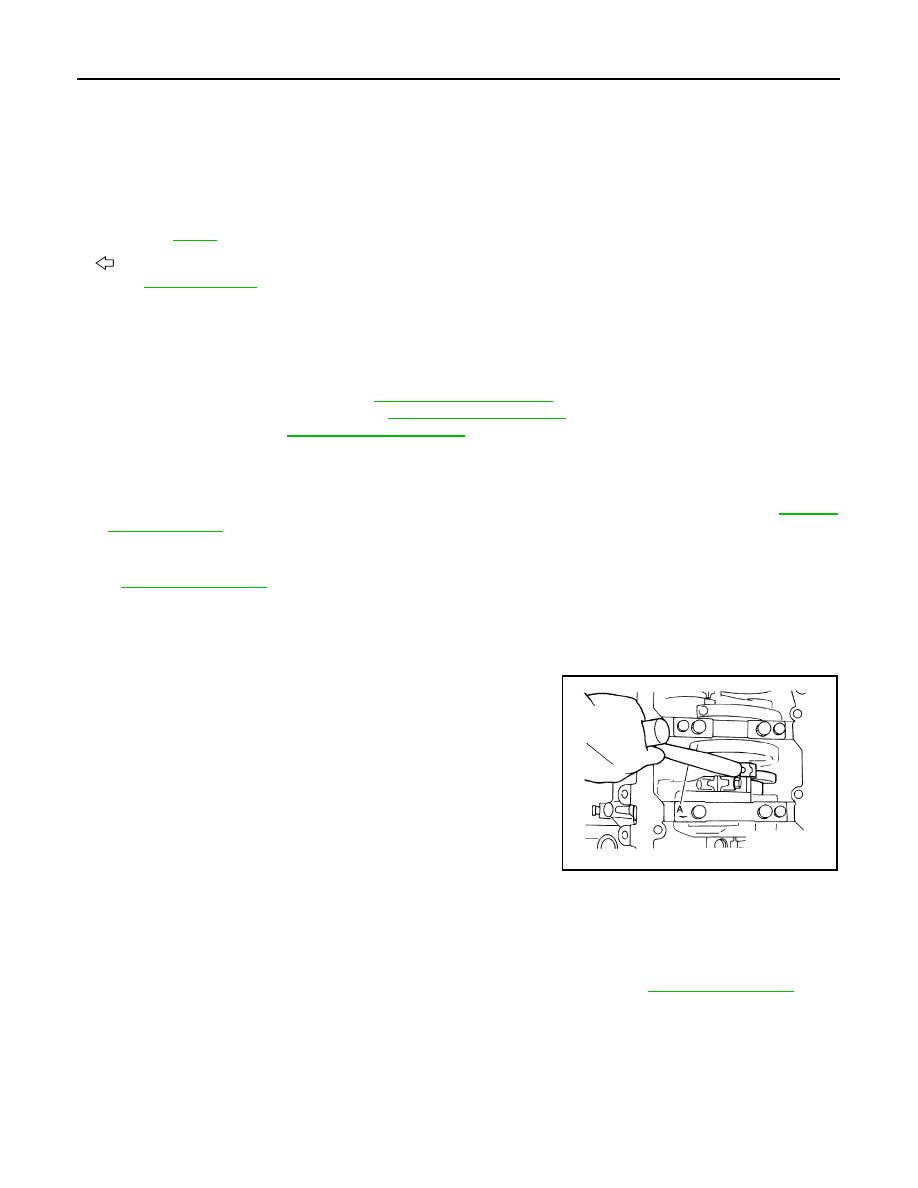
c.
Using a hammer handle (A) or similar tool, push piston and con-
necting rod assembly out to the cylinder head side.
CAUTION:
Be careful not to damage the cylinder wall and crankshaft
pin, resulting from an interference of the connecting rod big
end.
5.
Remove connecting rod bearings from connecting rod and connecting rod bearing cap.
CAUTION:
• Be careful not to drop connecting rod bearing, and to scratch the surface.
• Identify installation positions, and store them without mixing them up.
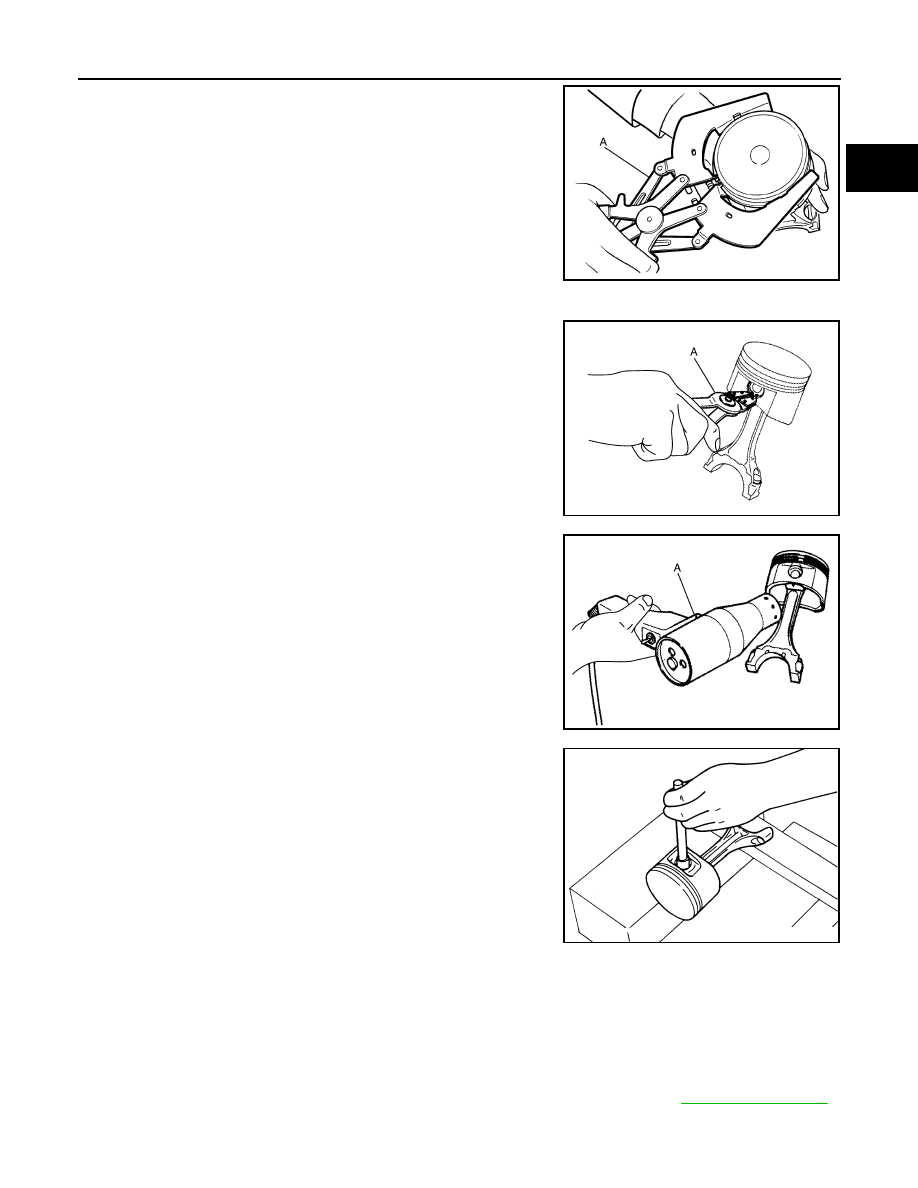
6.
Remove piston rings from piston.
• Before removing piston rings, check the piston ring side clearance. Refer to
.
10. Main bearing cap sub bolt
11. Main bearing cap bolt
12. Connecting rod cap bolt
13. Connecting rod cap
14. Connecting rod bearing
15. Connecting rod
16. Snap ring
17. Piston pin
18. Piston
19. Oil ring
20. Second ring
21. Top ring
22. Pilot converter
23. Piston oil jet
24. Drive plate
25. Reinforcement plate
26. Rear oil seal
27. Rear oil seal retainer
28. Cylinder block heater (for Canada)
A.
Refer to
B.
Chamfered
: Crankshaft side
for symbol marks in the figure.
JPBIA2475ZZ
CYLINDER BLOCK
EM-257
< UNIT DISASSEMBLY AND ASSEMBLY >
[VK50VE]
C
D
E
F
G
H
I
J
K
L
M
A
EM
N
P
O
• Use a piston ring expander (commercial service tool) (A).
CAUTION:
• When removing piston rings, be careful not to damage
piston.
• Be careful not to damage piston rings by expanding them
excessively.
7.
Remove piston from connecting rod as per the following:
a.
Using snap ring pliers (A), remove snap rings.
b.
Heat piston to 60 to 70
°
C (140 to 158
°
F) with an industrial use
dryer (A) or an equivalent.
c.
Push out piston pin using a stick that has an outer diameter of
approximately 20 mm (0.79 in).
8.
Remove rear oil seal and rear oil seal retainer assembly from cylinder block.
• Insert screwdriver or similar tool between rear end of crankshaft counter weight and rear oil seal
retainer, and separate liquid gasket to remove.
CAUTION:
Be careful not to damage the mating surfaces.
9.
Using screwdriver or similar tool, and lever off rear oil seal from rear oil seal retainer.
10. Remove main bearing cap as per the following:
• Before loosening cylinder block bolts, measure the crankshaft end play. Refer to
JPBIA0194ZZ
JPBIA0195ZZ
JPBIA0196ZZ
PBIC0262E
EM-258
< UNIT DISASSEMBLY AND ASSEMBLY >
[VK50VE]
CYLINDER BLOCK
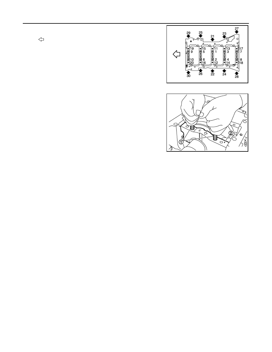
a.
Loosen side bolts starting from No. 30 to 21 to remove.
b.
Loosen main bearing cap sub bolts starting from No. 20 to 11 to
remove.
c.
Loosen main bearing cap bolts starting from No. 10 to 1 to
remove.
d.
Remove the main bearing cap.
• Insert bolts (1) into bolt holes, and then remove main bearing
cap (2) by lifting up and shaking forward and backward.
CAUTION:
Be careful not to damage the mounting surface.
11. Remove crankshaft.
12. Remove main bearings and thrust bearings from main bearing cap and cylinder block.
CAUTION:
• Be careful not to drop main bearing, and to scratch the surface.
• Identify installation positions, and store them without mixing them up.
13. Remove pilot converter using the pilot bushing puller (commercial service tool), if necessary.
14. Remove oil jet.
ASSEMBLY
1.
Fully air-blow engine coolant and engine oil passages in cylinder block, cylinder bore and crankcase to
remove any foreign material.
CAUTION:
Use goggles to protect your eyes.
: Engine front
JPBIA2146ZZ
JPBIA2478ZZ
CYLINDER BLOCK
EM-259
< UNIT DISASSEMBLY AND ASSEMBLY >
[VK50VE]
C
D
E
F
G
H
I
J
K
L
M
A
EM
N
P
O
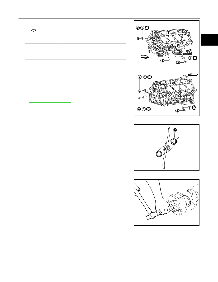
2.
Install each plug to cylinder block as shown in the figure.
• Tighten each plug as specified below.
• Replace washers (1), (5) with new ones.
• Apply sealant to the thread of water drain plug (3).
Use Genuine RTV Silicone Sealant or an equivalent. Refer
to
GI-16, "Recommended Chemical Products and Seal-
• Apply sealant to the thread of plug (4).
Use Genuine High Strength Thread Locking Sealant or an
equivalent. Refer to
3.
Install oil jet.
• Insert oil jet into cylinder block hole, and tighten the mounting
bolt on the corner side (A) first.
4.
Install pilot converter to crankshaft, if removed.
• With drift [outer diameter: approx. 35 mm (1.38 in)], press-fit
as far as it will go.
: Engine front
Part
Tightening torque
Plug (2)
78.0 N·m (8.0 kg-m, 58 ft-lb)
Water drain plug (3)
19.6 N·m (2.0 kg-m, 14 ft-lb)
Plug (4)
65.0 N·m (6.6 kg-m, 48 ft-lb)
JPBIA2121ZZ
JPBIA2147ZZ
EMP0569D
Нет комментариевНе стесняйтесь поделиться с нами вашим ценным мнением.
Текст