Infiniti FX35, FX50 (S51). Manual — part 1260
IP-8
< PRECAUTION >
PRECAUTIONS
PRECAUTION
PRECAUTIONS
Precaution for Supplemental Restraint System (SRS) "AIR BAG" and "SEAT BELT
PRE-TENSIONER"
INFOID:0000000005241034
The Supplemental Restraint System such as “AIR BAG” and “SEAT BELT PRE-TENSIONER”, used along
with a front seat belt, helps to reduce the risk or severity of injury to the driver and front passenger for certain
types of collision. This system includes seat belt switch inputs and dual stage front air bag modules. The SRS
system uses the seat belt switches to determine the front air bag deployment, and may only deploy one front
air bag, depending on the severity of a collision and whether the front occupants are belted or unbelted.
Information necessary to service the system safely is included in the “SRS AIR BAG” and “SEAT BELT” of this
Service Manual.
WARNING:
• To avoid rendering the SRS inoperative, which could increase the risk of personal injury or death in
the event of a collision which would result in air bag inflation, all maintenance must be performed by
an authorized NISSAN/INFINITI dealer.
• Improper maintenance, including incorrect removal and installation of the SRS, can lead to personal
injury caused by unintentional activation of the system. For removal of Spiral Cable and Air Bag
Module, see the “SRS AIR BAG”.
• Do not use electrical test equipment on any circuit related to the SRS unless instructed to in this
Service Manual. SRS wiring harnesses can be identified by yellow and/or orange harnesses or har-
ness connectors.
PRECAUTIONS WHEN USING POWER TOOLS (AIR OR ELECTRIC) AND HAMMERS
WARNING:
• When working near the Air Bag Diagnosis Sensor Unit or other Air Bag System sensors with the
ignition ON or engine running, DO NOT use air or electric power tools or strike near the sensor(s)
with a hammer. Heavy vibration could activate the sensor(s) and deploy the air bag(s), possibly
causing serious injury.
• When using air or electric power tools or hammers, always switch the ignition OFF, disconnect the
battery, and wait at least 3 minutes before performing any service.
Precaution Necessary for Steering Wheel Rotation after Battery Disconnect
INFOID:0000000005241035
NOTE:
• Before removing and installing any control units, first turn the push-button ignition switch to the LOCK posi-
tion, then disconnect both battery cables.
• After finishing work, confirm that all control unit connectors are connected properly, then re-connect both
battery cables.
• Always use CONSULT-III to perform self-diagnosis as a part of each function inspection after finishing work.
If a DTC is detected, perform trouble diagnosis according to self-diagnosis results.
For vehicle with steering lock unit, if the battery is disconnected or discharged, the steering wheel will lock and
cannot be turned.
If turning the steering wheel is required with the battery disconnected or discharged, follow the operation pro-
cedure below before starting the repair operation.
OPERATION PROCEDURE
1.
Connect both battery cables.
NOTE:
Supply power using jumper cables if battery is discharged.
2.
Turn the push-button ignition switch to ACC position.
(At this time, the steering lock will be released.)
3.
Disconnect both battery cables. The steering lock will remain released with both battery cables discon-
nected and the steering wheel can be turned.
4.
Perform the necessary repair operation.
PRECAUTIONS
IP-9
< PRECAUTION >
C
D
E
F
G
H
I
K
L
M
A
B
IP
N
O
P
5.
When the repair work is completed, re-connect both battery cables. With the brake pedal released, turn
the push-button ignition switch from ACC position to ON position, then to LOCK position. (The steering
wheel will lock when the push-button ignition switch is turned to LOCK position.)
6.
Perform self-diagnosis check of all control units using CONSULT-III.
Precaution
INFOID:0000000005241036
• Disconnect battery negative terminal in advance.
• Disconnect air bag system line in advance.
• Never tamper with or force air bag lid open, as this may adversely affect air bag performance.
• Be careful not to scratch pad and other parts.
• When removing or disassembling any part, be careful not to damage or deform it. Protect parts, which may
get in the way with a shop cloth.
• When removing parts with a screwdriver or other tool, cover the tool surface by vinyl tape to protect parts.
• Keep removed parts protected with a shop cloth.
• If a clip is deformed or damaged, replace it.
• If an unreusable part is removed, replace it with a new one.
• Tighten bolts and nuts firmly to the specified torque.
• After reassembly has been completed, make sure each part functions correctly.
• Remove stains in the following way.
Water-soluble stains:
Dip a soft cloth in warm water, and then squeeze it tightly. After wiping the stain, wipe with a soft dry cloth.
Oil stain:
Dissolve a synthetic detergent in warm water (density of 2 to 3%), dip the cloth, then clean off the stain with
the cloth. Next, dip the cloth in fresh water and squeeze it tightly. Then clean off the detergent completely.
Then wipe the area with a soft dry cloth.
• Never use any organic solvent, such as thinner or benzine.
IP-10
< PREPARATION >
PREPARATION
PREPARATION
PREPARATION
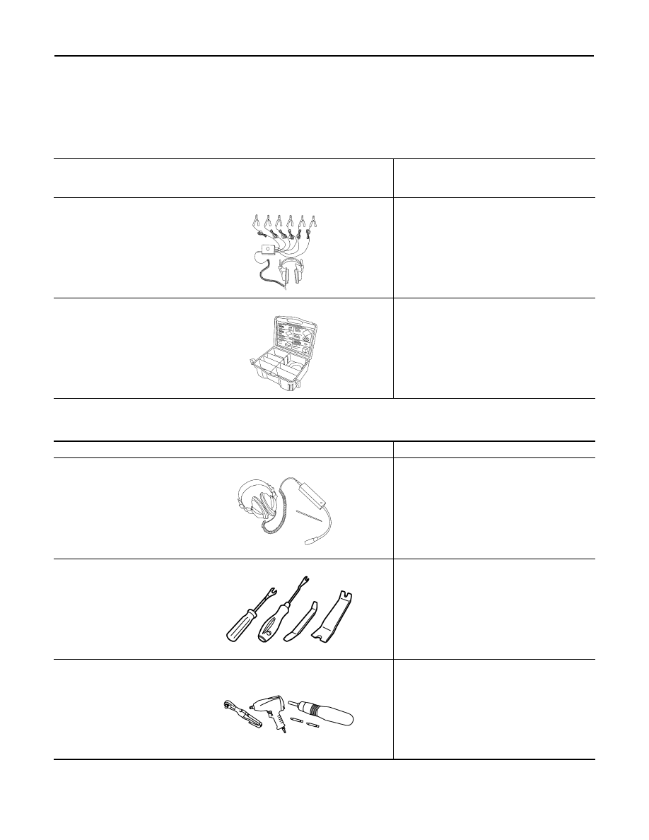
Special Service Tools
INFOID:0000000005241037
The actual shapes of Kent-Moore tools may differ from those of special service tools illustrated here.
Commercial Service Tools
INFOID:0000000005241038
Tool number
(Kent-Moore No.)
Tool name
Description
(J-39570)
Chassis ear
Locates the noise
(J-43980)
NISSAN Squeak and Rattle
Kit
Repairs the cause of noise
SIIA0993E
SIIA0994E
Tool name
Description
Engine ear
Locates the noise
Remover tool
Removes clips, pawls and metal clips
Power tool
SIIA0995E
JMKIA3050ZZ
PIIB1407E
INSTRUMENT PANEL ASSEMBLY
IP-11
< REMOVAL AND INSTALLATION >
C
D
E
F
G
H
I
K
L
M
A
B
IP
N
O
P
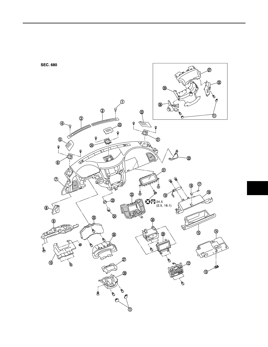
REMOVAL AND INSTALLATION
INSTRUMENT PANEL ASSEMBLY
Exploded View
INFOID:0000000005241039
JMJIA1971GB
Нет комментариевНе стесняйтесь поделиться с нами вашим ценным мнением.
Текст