Infiniti FX35, FX50 (S51). Manual — part 1261

IP-12
< REMOVAL AND INSTALLATION >
INSTRUMENT PANEL ASSEMBLY
Removal and Installation
INFOID:0000000005241040
WORK STEP
When removing instrument panel assembly, combination meter, AV C/U (audio unit), instrument finisher A and
center console assembly take steps in the order shown by the number below.
1.
Optical sensor
2.
Front defroster grille RH
3.
Front defroster grille LH
4.
Sunload sensor
5.
Speaker grille LH
6.
Front squawker LH
7.
Instrument panel assembly
8.
Instrument side finisher LH
9.
Instrument lower panel LH
10. Instrument lower cover LH
11.
Steering column mask
12. Cluster lid C
13. Illumination lamp
14. Instrument lower cover RH
15. Glove box assembly
16. Instrument lower panel RH
17. Socket and bulb
18. Illumination lamp
19. Glove box damper
20. Instrument side finisher RH
21. Front squawker RH
22. Speaker grille RH
23. Center speaker grille
24. Center speaker
25. Combination meter
26. Cluster lid A
27. Steering column upper cover
28. Steering column lower cover
29. Display unit
30. AV control unit (audio unit)
31. Front passenger air bag module
32. Cluster lid D
33. Ignition switch cover
34. Push button ignition switch
35. Steering column side cover RH
36. Steering column side cover LH
Refer to
for symbols in the figure.
PARTS
INSTRUMENT
PANEL
ASSEMBLY
COMBINATION
METER
AV control unit
(audio unit)
INSTRUMENT
FINISHER A
CENTER
CONSOLE
ASSEMBLY
Selector lever knob
[1]
[1]
[1]
Console upper finisher
[2]
[2]
[2]
Console finisher assembly
[3]
[3]
[3]
Console switch finisher
[4]
[4]
Console pocket assembly
[5]
[4]
[5]
Console rear finisher
[6]
[6]
Rear ventilator duct
[7]
[7]
Center console assembly
[8]
[8]
Instrument lower cover LH
[9]
[1]
[1]
Instrument lower panel LH
[10]
[2]
[2]
Front body side welt LH
[11]
[3]
Instrument side finisher LH
[12]
[4]
Instrument finisher A
[5]
Front pillar garnish LH
[13]
Speaker grille LH
[14]
Front squawker LH
[15]
Steering wheel
[16]
Steering column cover
[17]
[3]
Combination switch
[18]
[4]
Paddle switch LH/RH
[19]
Cluster lid A
[20]
[5]
Combination meter
[21]
[6]
Center speaker grille
[22]
Center speaker
[23]
Inside key antenna
[24]
Cluster lid C
[25]
[5]
INSTRUMENT PANEL ASSEMBLY
IP-13
< REMOVAL AND INSTALLATION >
C
D
E
F
G
H
I
K
L
M
A
B
IP
N
O
P
[ ]: Number indicates step in removal procedures.
REMOVAL
1.
Remove selector lever knob. Refer to
TM-169, "Removal and Installation"
.
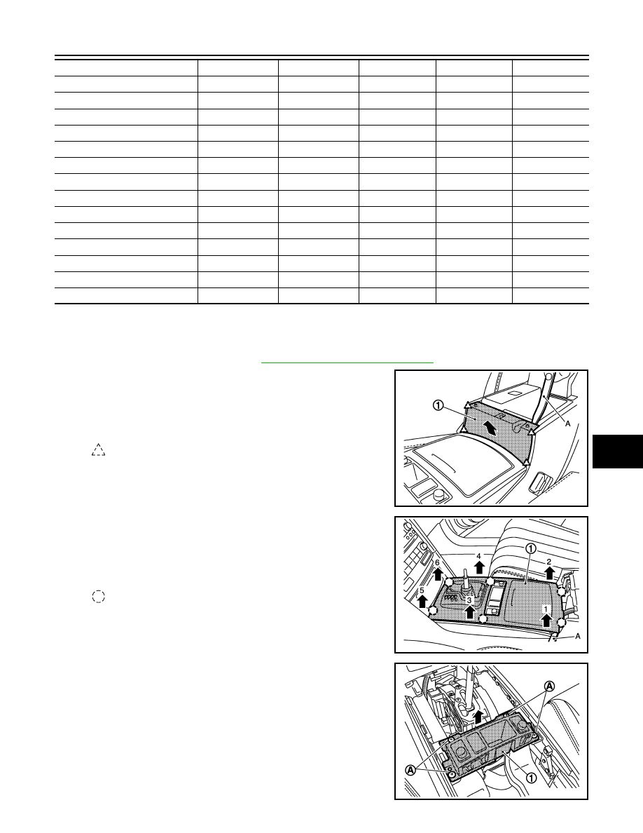
2.
Remove console upper finisher.
• Open the console lid.
• Remove console upper finisher (1) fixing pawls with remover
tool (A).
• Pull back console upper finisher.
3.
Remove console finisher assembly.
• Remove console finisher assembly (1) fixing clips with
remover tool (A).
• Pull up console finisher assembly.
• Disconnect harness connector.
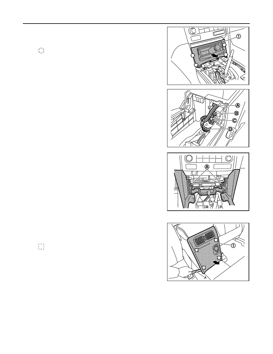
4.
Remove console switch finisher.
• Remove console switch finisher (1) fixing screws (A).
• Pull up console switch finisher.
• Disconnect harness connectors.
Cluster lid D
[26]
[6]
Display unit
[27]
[7]
AV control unit (audio unit)
[28]
[8]
Push button ignition switch
[29]
Front defroster grille LH
[30]
Front defroster grille RH
[31]
Glove box assembly
[32]
Instrument lower cover RH
[33]
Instrument lower panel RH
[34]
Front body side welt RH
[35]
Instrument side finisher RH
[36]
Front pillar garnish RH
[37]
Speaker grille RH
[38]
Front squawker RH
[39]
Instrument panel assembly
[40]
: Pawl
JMJIA1972ZZ
: Clip
JMJIA1973ZZ
JMJIA1974ZZ
IP-14
< REMOVAL AND INSTALLATION >
INSTRUMENT PANEL ASSEMBLY
5.
Remove console pocket assembly.
• Pull back console pocket assembly (1), and disengage clips.
• Disconnect harness connector.
6.
Disconnect USB connector harness connector (A).
7.
Disconnect auxiliary input jacks harness connector (B).
8.
Disconnect console power socket harness connector (C).
9.
Disconnect DVD player harness connector (D).
10. Remove center console assembly fixing screws (A).
11. Put front seat to front must position.
12. Remove console rear finisher.
• Pull back the console rear finisher (1) with remover tool (A).
• Disconnect harness connectors.
: Clip
JMJIA1975ZZ
JMJIA1976ZZ
JMJIA1977ZZ
: Metal clip
JMJIA1978ZZ
INSTRUMENT PANEL ASSEMBLY
IP-15
< REMOVAL AND INSTALLATION >
C
D
E
F
G
H
I
K
L
M
A
B
IP
N
O
P
13. Remove rear ventilator duct (1).
Refer to
VTL-16, "REAR VENTILATOR DUCT 1 : Removal and
.
14. Remove center console fixing screws (A).
15. Remove center console assembly.
Pull back and lift up center console assembly (1).
16. Put front seat to rear most position.
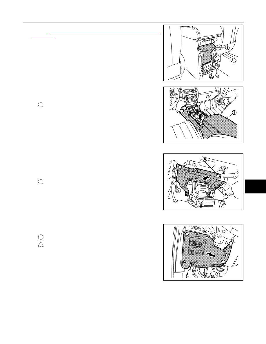
17. Remove instrument lower cover LH (VK engine model only).
• Remove instrument lower cover LH (1) fixing clips (A) and
plastic nuts (B).
• Pull back instrument lower cover LH.
18. Remove instrument lower panel LH.
• Remove hood opener lever fixing bolts.
• Pull back instrument lower panel LH (1).
JMJIA1979ZZ
: Clip
JMJIA1980ZZ
: Clip
JMJIA2303ZZ
: Clip
: Pawl
JMJIA1981ZZ
Нет комментариевНе стесняйтесь поделиться с нами вашим ценным мнением.
Текст