Infiniti FX35, FX50 (S51). Manual — part 1080
FAX-18
< REMOVAL AND INSTALLATION >
[AWD]
FRONT DRIVE SHAFT BOOT
FRONT DRIVE SHAFT BOOT
Exploded View
INFOID:0000000005248990
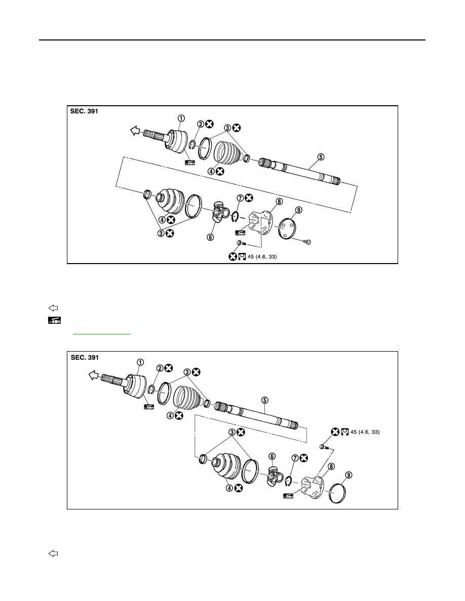
LEFT SIDE
VQ35HR
VK50VE
JPDIF0168GB
1.
Joint sub-assembly
2.
Circular clip
3.
Boot band
4.
Boot
5.
Shaft
6.
Spider assembly
7.
Snap ring
8.
Housing
9.
Plug
: Wheel side
: NISSAN genuine grease or an equivalent.
for symbols not described on the above.
JPDIF0191GB
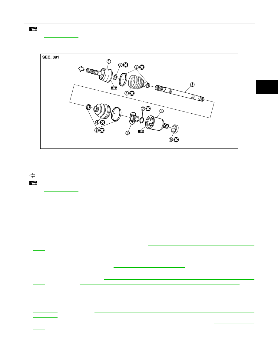
1.
Joint sub-assembly
2.
Circular clip
3.
Boot band
4.
Boot
5.
Shaft
6.
Spider assembly
7.
Snap ring
8.
Housing
9.
Plug
: Wheel side
FRONT DRIVE SHAFT BOOT
FAX-19
< REMOVAL AND INSTALLATION >
[AWD]
C
E
F
G
H
I
J
K
L
M
A
B
FAX
N
O
P
RIGHT SIDE
WHEEL SIDE
WHEEL SIDE : Removal and Installation
INFOID:0000000005248991
REMOVAL
Left Side
1.
Remove tires with power tool.
2.
Remove wheel sensor and sensor harness. Refer to
BRC-131, "FRONT WHEEL SENSOR : Exploded
.
CAUTION:
Never pull on wheel sensor harness.
3.
Remove brake hose bracket. Refer to
BR-20, "FRONT : Exploded View"
.
4.
Remove caliper assembly mounting bolts with power tool. Hang caliper assembly in a place where it will
not interfere with work. Refer to
BR-43, "BRAKE CALIPER ASSEMBLY (2 PISTON TYPE) : Exploded
BR-47, "BRAKE CALIPER ASSEMBLY (4 PISTON TYPE) : Exploded View"
(4 pis-
ton type).
CAUTION:
Never depress brake pedal while brake caliper is removed.
5.
Remove disc rotor. Refer to
BR-44, "BRAKE CALIPER ASSEMBLY (2 PISTON TYPE) : Removal and
(2 piston type),
BR-48, "BRAKE CALIPER ASSEMBLY (4 PISTON TYPE) : Removal and
(4 piston type).
6.
Remove cotter pin, and then loosen wheel hub lock nut with a power tool. Refer to
.
: NISSAN genuine grease or an equivalent.
Refer to
for symbols not described on the above.
1.
Joint sub-assembly
2.
Circular clip
3.
Boot band
4.
Boot
5.
Shaft
6.
Spider assembly
7.
Snap ring
8.
Housing
9.
Dust shield
: Wheel side
: NISSAN genuine grease or an equivalent.
Refer to
for symbols not described on the above.
JPDIF0197ZZ
FAX-20
< REMOVAL AND INSTALLATION >
[AWD]
FRONT DRIVE SHAFT BOOT
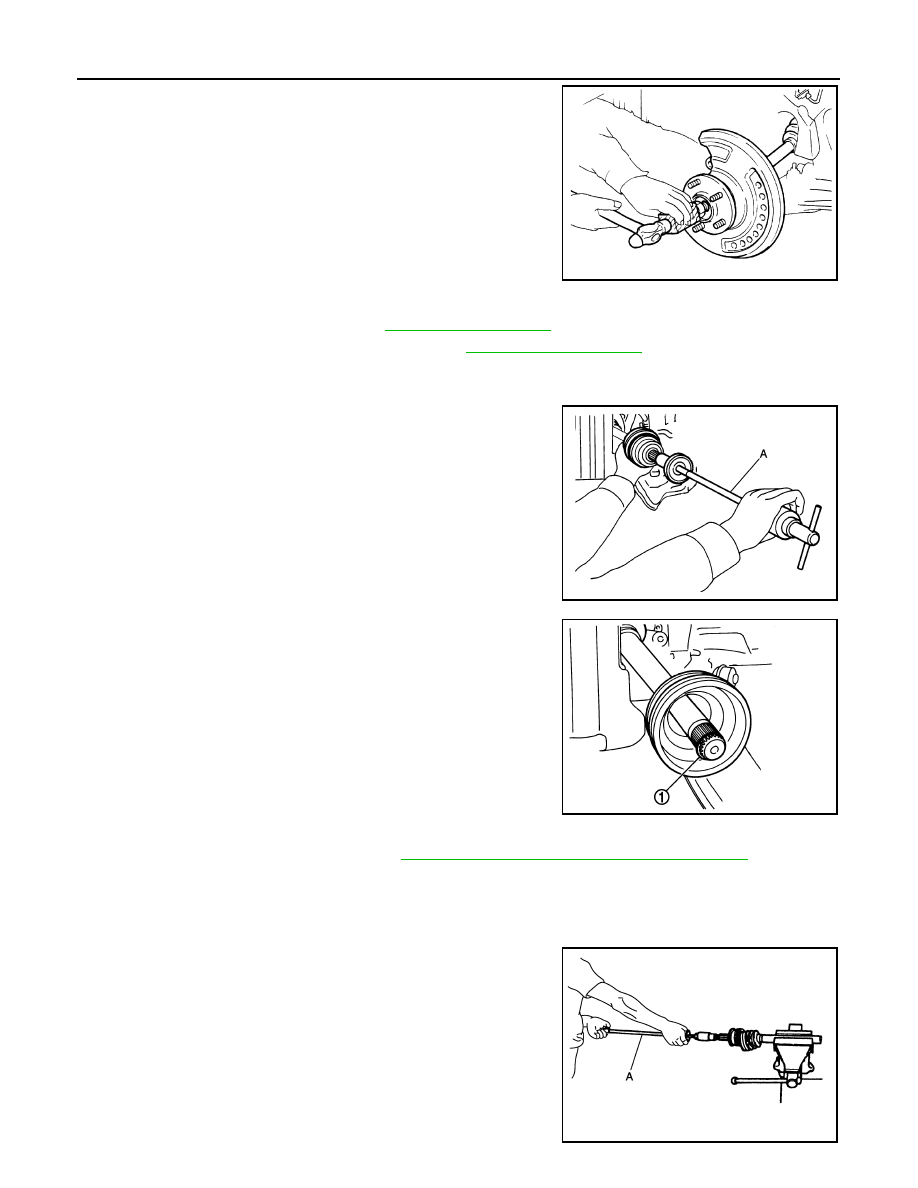
7.
Patch wheel hub lock nut with a piece of wood. Hammer the
wood to disengage wheel hub and bearing assembly from drive
shaft.
CAUTION:
• Never place drive shaft joint at an extreme angle. Also be
careful not to overextend slide joint.
• Never allow drive shaft to hang down without support for
joint sub-assembly, shaft and the other parts.
NOTE:
Use suitable puller if wheel hub and bearing assembly and drive
shaft cannot be separated even after performing the above pro-
cedure.
8.
Remove wheel hub lock nut.
9.
Remove steering outer socket. Refer to
10. Separate upper link from steering knuckle. Refer to
.
11. Remove drive shaft from wheel hub and bearing assembly.
12. Remove boot bands, and then remove boot from joint sub-assembly.
13. Screw drive shaft puller (commercial service tool) (A) 30 mm
(1.18 in) or more into the thread of joint sub-assembly, and pull
joint sub-assembly from shaft.
CAUTION:
• Align a sliding hammer and drive shaft and remove them
by pulling firmly and uniformly.
• If joint sub-assembly cannot be pulled out, try after
removing drive shaft from vehicle.
14. Remove circular clip (1) from shaft.
15. Remove boot from shaft.
Right Side
1.
Remove drive shaft from vehicle. Refer to
FAX-28, "RIGHT SIDE : Removal and Installation"
2.
Fix shaft with a vise.
CAUTION:
Protect shaft when fixing with a vise using aluminum or copper plates.
3.
Remove boot bands, and then remove boot from joint sub-assembly.
4.
Screw drive shaft puller (commercial service tool) (A) 30 mm
(1.18 in) or more into the thread of joint sub-assembly, and pull
joint sub-assembly from shaft.
CAUTION:
• Align a sliding hammer and drive shaft and remove them
by pulling firmly and uniformly.
• If joint sub-assembly cannot be removed after five or
more unsuccessful attempts, replace shaft and joint sub
assembly as a set.
5.
Remove circular clip from shaft.
6.
Remove boot from shaft.
JPDIG0070ZZ
JPDIF0258ZZ
JPDIF0007ZZ
JPDIG0151ZZ
FRONT DRIVE SHAFT BOOT
FAX-21
< REMOVAL AND INSTALLATION >
[AWD]
C
E
F
G
H
I
J
K
L
M
A
B
FAX
N
O
P
INSTALLATION
Left Side
1.
Clean the old grease on joint sub-assembly with paper waste.
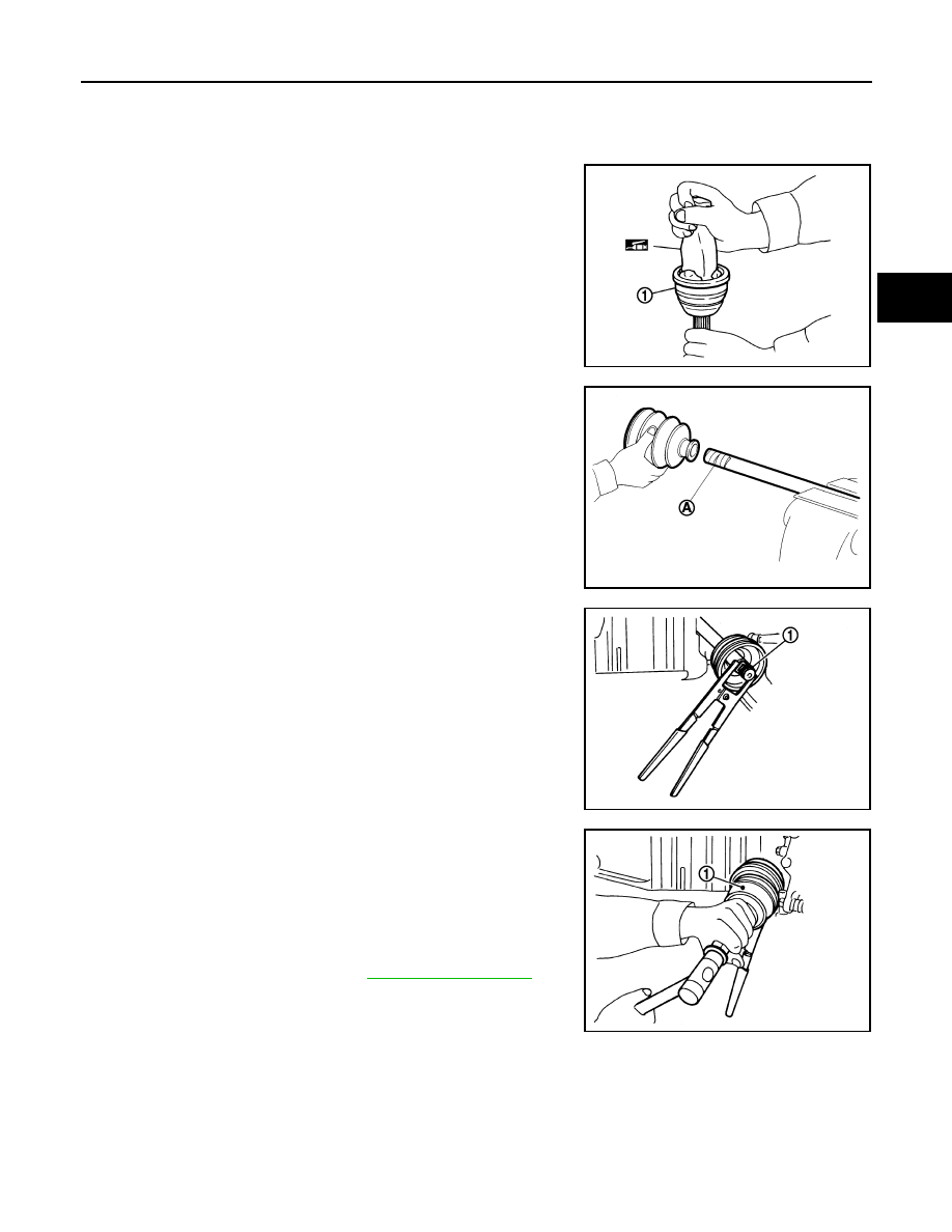
2.
Fill serration slot joint sub-assembly (1) with NISSAN genuine
grease or equivalent until the serration slot and ball groove
become full to the brim.
CAUTION:
After applying grease, use a shop cloth to wipe off old
grease that has oozed out.
3.
Install boot and boot bands to shaft.
CAUTION:
• Wrap serration on shaft with tape (A) to protect the boot
from damage.
• Never reuse boot and boot band.
4.
Remove the tape wrapped around the serration on shaft.
5.
Position circular clip (1) on groove at the shaft edge.
CAUTION:
Never reuse circular clip.
NOTE:
Drive joint inserter is recommended when installing circular clip.
6.
Align both center axles of the shaft edge and joint sub-assembly.
Then assemble shaft with joint sub-assembly holding circular
clip.
7.
Install joint sub-assembly (1) to shaft using plastic hammer.
CAUTION:
Confirm that joint sub-assembly is correctly engaged while
rotating drive shaft.
8.
Apply the specified amount of grease into the boot inside from
large diameter side of boot.
JPDIF0008ZZ
JPDIF0009ZZ
JPDIF0010ZZ
Grease amount
: Refer to
.
JPDIF0011ZZ
Нет комментариевНе стесняйтесь поделиться с нами вашим ценным мнением.
Текст