Infiniti FX35, FX50 (S51). Manual — part 1079
FAX-14
< PERIODIC MAINTENANCE >
[AWD]
FRONT WHEEL HUB AND KNUCKLE
PERIODIC MAINTENANCE
FRONT WHEEL HUB AND KNUCKLE
Inspection
INFOID:0000000005248985
MOUNTING INSPECTION
Make sure that the mounting conditions (looseness, backlash) of each component and component conditions
(wear, damage) are normal.
WHEEL BEARING INSPECTION
• Move wheel hub and bearing assembly in the axial direction by hand. Make sure there is no looseness of
wheel bearing.
• Rotate wheel hub and make sure there is no unusual noise or other irregular conditions. If there is any of
irregular conditions, replace wheel hub and bearing assembly.
Axial end play
: Refer to
.
FRONT DRIVE SHAFT
FAX-15
< PERIODIC MAINTENANCE >
[AWD]
C
E
F
G
H
I
J
K
L
M
A
B
FAX
N
O
P
FRONT DRIVE SHAFT
Inspection
INFOID:0000000005248986
• Check drive shaft mounting point and joint for looseness and other damage.
• Check boot for cracks and other damage.
CAUTION:
Replace entire drive shaft assembly when noise or vibration occur from drive shaft.
FAX-16
< REMOVAL AND INSTALLATION >
[AWD]
FRONT WHEEL HUB AND KNUCKLE
REMOVAL AND INSTALLATION
FRONT WHEEL HUB AND KNUCKLE
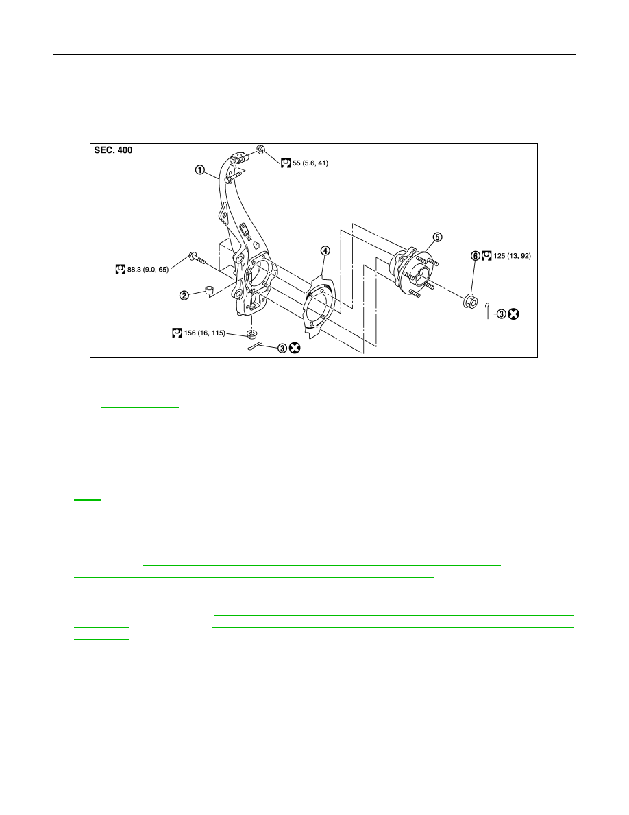
Exploded View
INFOID:0000000005248987
Removal and Installation
INFOID:0000000005248988
REMOVAL
1.
Remove tires with power tool.
2.
Remove wheel sensor and sensor harness. Refer to
BRC-131, "FRONT WHEEL SENSOR : Exploded
.
CAUTION:
Never pull on wheel sensor harness.
3.
Remove brake hose bracket. Refer to
BR-20, "FRONT : Exploded View"
.
4.
Remove caliper assembly with power tool. Hang caliper assembly in a place where it will not interfere with
work. Refer to
BR-43, "BRAKE CALIPER ASSEMBLY (2 PISTON TYPE) : Exploded View"
BR-47, "BRAKE CALIPER ASSEMBLY (4 PISTON TYPE) : Exploded View"
(4 piston type).
CAUTION:
Never depress brake pedal while brake caliper is removed.
5.
Remove disc rotor. Refer to
BR-44, "BRAKE CALIPER ASSEMBLY (2 PISTON TYPE) : Removal and
(2 piston type),
BR-48, "BRAKE CALIPER ASSEMBLY (4 PISTON TYPE) : Removal and
(4 piston type).
6.
Remove cotter pin, and then loosen wheel hub lock nut with power tool.
1.
Steering knuckle
2.
Ball seat
3.
Cotter pin
4.
Splash guard
5.
Wheel hub and bearing assembly
6.
Wheel hub lock nut
Refer to
for symbols in the figure.
JPDIF0190GB
FRONT WHEEL HUB AND KNUCKLE
FAX-17
< REMOVAL AND INSTALLATION >
[AWD]
C
E
F
G
H
I
J
K
L
M
A
B
FAX
N
O
P
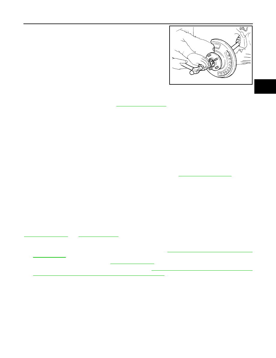
7.
Patch wheel hub lock nut with a piece of wood. Hammer the
wood to disengage wheel hub and bearing assembly from drive
shaft.
CAUTION:
• Never place drive shaft joint at an extreme angle. Also be
careful not to overextend slide joint.
• Never allow drive shaft to hang down without support for
or joint sub-assembly, shaft and the other parts.
NOTE:
Use suitable puller, if wheel hub and bearing assembly and drive
shaft cannot be separated even after performing the above pro-
cedure.
8.
Remove wheel hub lock nut.
9.
Remove wheel hub and bearing assembly, and then remove splash guard.
10. Remove steering outer socket. Refer to
11. Remove cotter pin of transverse link and steering knuckle, and then loosen nut.
12. Separate steering knuckle from upper link.
13. Separate steering knuckle link from transverse so as not to damage ball joint boot using the ball joint
remover, and remove steering knuckle.
CAUTION:
Temporarily tighten the nut to prevent damage to threads and to prevent the ball joint remover
from suddenly coming off.
INSTALLATION
Note the following, and install in the reverse order of the removal.
• Perform the final tightening of each of parts under unladen conditions, which were removed when removing
wheel hub and bearing assembly and steering knuckle.
• Install drive shaft using tightening torque of wheel hub lock nut. Refer to
.
CAUTION:
Be sure to use torque wrench to tighten the wheel hub lock nut. Never use a power tool.
• Never reuse cotter pin.
Inspection
INFOID:0000000005248989
INSPECTION AFTER REMOVAL
Check components for deformation, cracks, and other damage. Replace it if necessary.
Ball Joint Inspection
Check boots of transverse link and steering outer socket ball joint for breakage, axial play, and torque. Refer to
INSPECTION AFTER INSTALLATION
1.
Check wheel sensor harness for proper connection. Refer to
BRC-131, "FRONT WHEEL SENSOR :
.
2.
Check the wheel alignment. Refer to
3.
Adjust neutral position of steering angle sensor. Refer to
BRC-9, "ADJUSTMENT OF STEERING ANGLE
SENSOR NEUTRAL POSITION : Special Repair Requirement"
.
JPDIG0070ZZ
Нет комментариевНе стесняйтесь поделиться с нами вашим ценным мнением.
Текст