Infiniti FX35, FX50 (S51). Manual — part 1494
ENCODER
PWC-37
< DTC/CIRCUIT DIAGNOSIS >
[FRONT & REAR WINDOW ANTI-PINCH]
C
D
E
F
G
H
I
J
L
M
A
B
PWC
N
O
P
4.
CHECK GROUND CIRCUIT 1
1.
Turn ignition switch OFF.
2.
Check continuity between rear power window motor RH harness connector and ground.
Is the inspection result normal?
YES
>> Replace rear power window motor RH. Refer to
GW-27, "Removal and Installation"
.
NO
>> GO TO 6.
5.
CHECK ENCORDER POWER SUPPLY CIRCUIT 2
1.
Turn ignition switch OFF.
2.
Disconnect rear power window switch RH connector.
3.
Check continuity between rear power window switch RH harness connector and rear power window motor
RH harness connector.
4.
Check continuity between rear power window switch RH harness connector and ground.
Is the inspection result normal?
YES
>> Replace rear power window switch RH. Refer to
PWC-138, "Removal and Installation"
.
NO
>> Repair or replace harness.
6.
CHECK GROUND CIRCUIT 2
1.
Disconnect rear power window switch RH harness connector.
2.
Check continuity between rear power window switch RH harness connector and rear power window motor
RH harness connector.
Is the inspection result normal?
YES
>> Replace rear power window switch RH. Refer to
PWC-138, "Removal and Installation"
.
NO
>> Repair or replace harness.
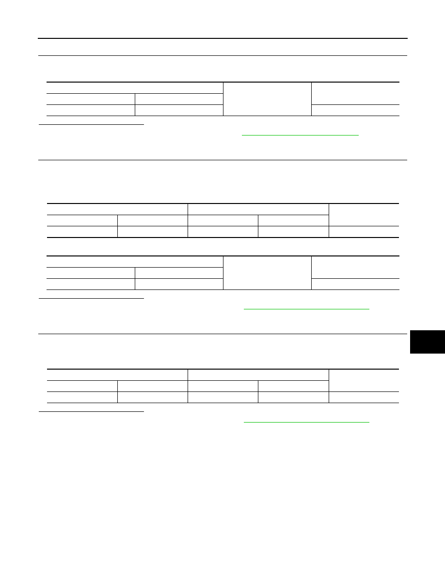
Rear power window motor RH
Ground
Continuity
Connector
Terminal
D72
4
Existed
Rear power window switch RH
Rear power window motor RH
Continuity
Connector
Terminal
Connector
Terminal
D77
4
D72
2
Existed
Rear power window switch RH
Ground
Continuity
Connector
Terminal
D77
4
Not existed
Rear power window switch RH
Rear power window motor RH
Continuity
Connector
Terminal
Connector
Terminal
D77
3
D72
4
Existed
PWC-38
< DTC/CIRCUIT DIAGNOSIS >
[FRONT & REAR WINDOW ANTI-PINCH]
DOOR KEY CYLINDER SWITCH
DOOR KEY CYLINDER SWITCH
Description
INFOID:0000000005248190
Power window main switch detects condition of the door key cylinder switch and transmits to BCM as the
LOCK or UNLOCK signals.
Component Function Check
INFOID:0000000005248191
1.
CHECK DOOR KEY CYLINDER SWITCH INPUT SIGNAL
Check (“KEY CYL LK-SW”, “KEY CYL UN-SW”) in “DATA MONITOR” mode for “POWER DOOR LOCK SYS-
TEM” with CONSULT-III. Refer to
DLK-53, "DOOR LOCK : CONSULT-III Function (BCM - DOOR LOCK)"
Is the inspection result normal?
YES
>> Door key cylinder switch is OK.
NO
>> Refer to
.
Diagnosis Procedure
INFOID:0000000005248192
1.
CHECK DOOR KEY CYLINDER SWITCH SIGNAL
1.
Turn ignition switch OFF.
2.
Disconnect front door lock assembly (driver side) (key cylinder switch) connect.
3.
Turn ignition switch ON.
4.
Check voltage between front door lock assembly (driver side) (key cylinder switch) harness connector and
ground.
Is the inspection result normal?
YES
>> GO TO 3.
NO
>> GO TO 2.
2.
CHECK DOOR KEY CYLINDER SWITCH CIRCUIT
1.
Turn ignition switch OFF.
2.
Disconnect power window main switch connector.
3.
Check continuity between power window main switch harness connector and front door lock assembly
(driver side) (key cylinder switch) harness connector.
4.
Check continuity between power window main switch harness connector and ground.
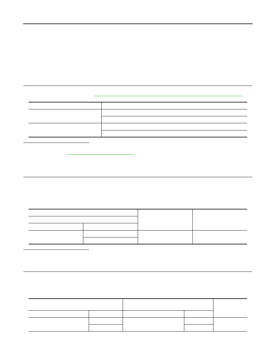
Monitor item
Condition
KEY CYL LK-SW
Lock
: ON
Neutral / Unlock
: OFF
KEY CYL UN-SW
Unlock
: ON
Neutral / Lock
: OFF
(+)
(–)
Voltage (V)
(Approx.)
Front door lock assembly (driver side) (key cylinder switch)
Connector
Terminal
D15
5
Ground
5
6
Power window main switch
Front door lock assembly (driver side) (key cylinder
switch)
Continuity
Connector
Terminal
Connector
Terminal
D8
4
D15
6
Existed
6
5
DOOR KEY CYLINDER SWITCH
PWC-39
< DTC/CIRCUIT DIAGNOSIS >
[FRONT & REAR WINDOW ANTI-PINCH]
C
D
E
F
G
H
I
J
L
M
A
B
PWC
N
O
P
Is the inspection result normal?
YES
>> Replace power window main switch. Refer to
PWC-136, "Removal and Installation"
NO
>> Repair or replace harness.
3.
CHECK DOOR KEY CYLINDER SWITCH GROUND CIRCUIT
Check continuity between front door lock assembly (driver side) (key cylinder switch) harness connector and
ground.
Is the inspection result normal?
YES
>> GO TO 4.
NO
>> Repair or replace harness.
4.
CHECK DOOR KEY CYLINDER SWITCH
Check front door lock assembly (driver side) (key cylinder switch).
Refer to
PWC-39, "Component Inspection"
Is the inspection result normal?
YES
>> GO TO 5.
NO
>> Replace front door lock assembly (driver side) (key cylinder switch). Refer to
LOCK : Removal and Installation"
.
5.
CHECK INTERMITTENT INCIDENT
GI-36, "Intermittent Incident"
.
>> INSPECTION END
Component Inspection
INFOID:0000000005248193
COMPONENT INSPECTION
1.
CHECK DOOR KEY CYLINDER SWITCH
1.
Turn ignition switch OFF.
2.
Disconnect front door lock assembly (driver side) (key cylinder switch) connector.
3.
Check front door lock assembly (driver side) (key cylinder switch).
Is the inspection result normal?
YES
>> INSPECTION END
NO
>> Replace front door lock assembly (driver side) (key cylinder switch). Refer to
LOCK : Removal and Installation"
.
Power window main switch
Ground
Continuity
Connector
Terminal
D8
4
Not existed
6
Front door lock assembly (driver side) (key cylinder switch)
Ground
Continuity
Connector
Terminal
D15
4
Existed
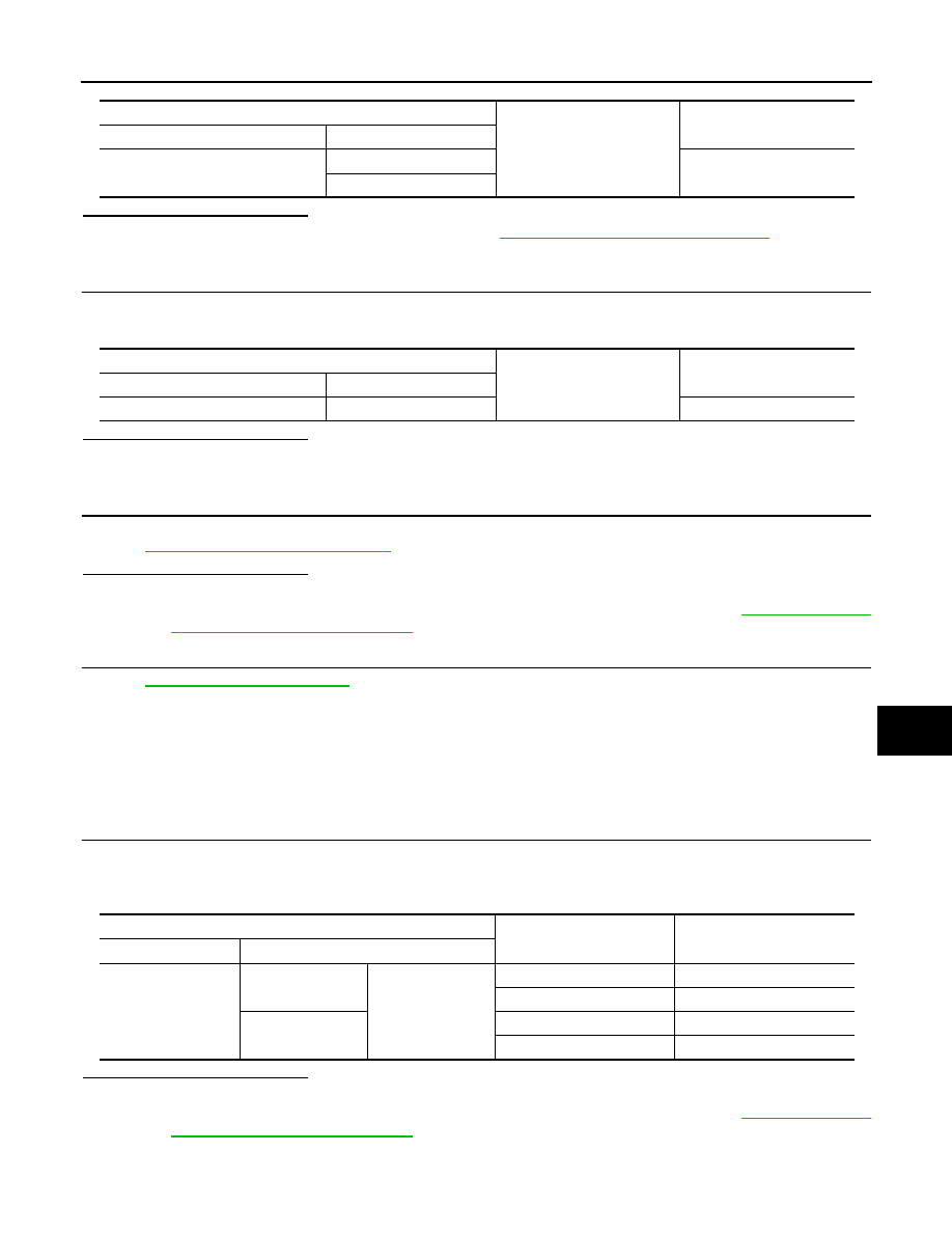
Front door lock assembly (driver side) (key cylinder switch)
Key position
Continuity
Connector
Terminal
D15
5
4
Unlock
Existed
Neutral / Lock
Not existed
6
Lock
Existed
Neutral / Unlock
Not existed
PWC-40
< DTC/CIRCUIT DIAGNOSIS >
[FRONT & REAR WINDOW ANTI-PINCH]
POWER WINDOW SERIAL LINK
POWER WINDOW SERIAL LINK
POWER WINDOW MAIN SWITCH
POWER WINDOW MAIN SWITCH : Description
INFOID:0000000005248194
Power window main switch, front power window switch (passenger side), rear power window switch and BCM
transmit and receive the signal by power window serial link.
The signal mentioned below is transmitted from BCM to power window main switch, front power window
switch (passenger side) and rear power window switch.
• Keyless power window down signal
The signal mentioned below is transmitted from power window main switch to front power window switch (pas-
senger side) and rear power window switch.
• Front passenger side door window and rear door window operation signal
• Power window control by key cylinder switch signal
• Power window lock switch signal
• Retained power operation signal
POWER WINDOW MAIN SWITCH : Component Function Check
INFOID:0000000005248195
1.
CHECK POWER WINDOW SWITCH OUTPUT SIGNAL
With CONSULT-III
Check (“CDL LOCK SW ”, “CDL UNLOCK SW”) in “DATA MONITOR” mode for “POWER DOOR LOCK SYS-
TEM” with CONSULT-III. Refer to
DLK-53, "DOOR LOCK : CONSULT-III Function (BCM - DOOR LOCK)"
Is the inspection result normal?
YES
>> Power window serial link is OK.
NO
>> Refer to
PWC-40, "POWER WINDOW MAIN SWITCH : Diagnosis Procedure"
POWER WINDOW MAIN SWITCH : Diagnosis Procedure
INFOID:0000000005248196
1.
CHECK POWER WINDOW SWITCH INPUT SIGNAL
1.
Turn ignition switch OFF.
2.
Disconnect power window main switch connector.
3.
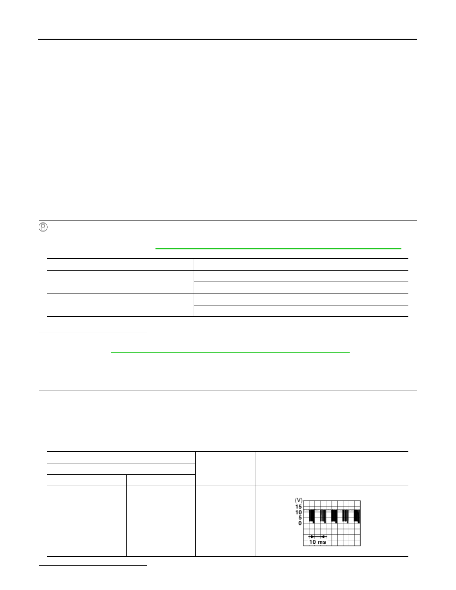
Check signal between power window main switch harness connector and ground with oscilloscope when
door lock and unlock switch (driver side and passenger side) is turned to “LOCK” or “UNLOCK”.
4.
Check that signals which are shown in the figure below can be detected during 10 seconds just after door
lock and unlock switch (driver side and passenger side) is turned to “LOCK” or “UNLOCK”.
Is the inspection result normal?
Monitor item
Condition
CDL LOCK SW
LOCK
: ON
UNLOCK
: OFF
CDL UNLOCK SW
LOCK
: OFF
UNLOCK
: ON
(+)
(–)
Signal
(Reference value)
Power window main switch
Connector
Terminal
D8
14
Ground
JPMIA0013GB
Нет комментариевНе стесняйтесь поделиться с нами вашим ценным мнением.
Текст