Infiniti FX35, FX50 (S51). Manual — part 285
BRM-18
< REMOVAL AND INSTALLATION >
BODY ALIGNMENT
BODY ALIGNMENT
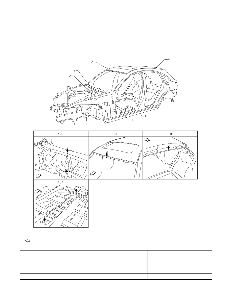
Body Center Marks
INFOID:0000000005248952
A mark is placed on each part of the body to indicate the vehicle center. When repairing the vehicle frame
(members, pillars, etc.) damaged by an accident which it enables more accurate and effective repair by using
these marks together with body alignment specifications.
Unit: mm (in)
: Vehicle front
Points
Portion
Marks
A
Upper dash
Embossment
B
Upper dash crossmember
Bead
C
Front roof
Embossment
D
Rear roof
Indent
JSKIA0660ZZ
BODY ALIGNMENT
BRM-19
< REMOVAL AND INSTALLATION >
C
D
E
F
G
H
I
J
L
M
A
B
BRM
N
O
P
Description
INFOID:0000000005248953
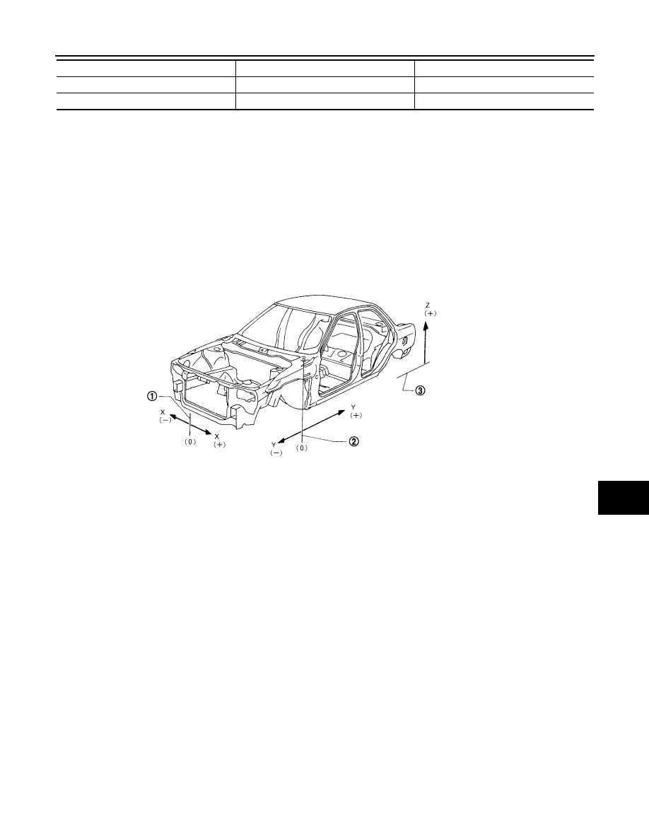
• All dimensions indicated in the figures are actual.
• When using a tracking gauge, adjust both pointers to equal length. Then check the pointers and gauge itself
to make sure there is no free play.
• When a measuring tape is used, check to be sure there is no elongation, twisting or bending.
• Measurements should be taken at the center of the mounting holes.
• An asterisk (*) following the value at the measuring point indicates that the measuring point on the other side
is symmetrically the same value.
• The coordinates of the measurement points are the distances measured from the standard line of
″
X
″
,
″
Y
″
and
″
Z
″
.
•
″
Z
″
: Imaginary base line [200 mm (7.87 in) below datum line (
″
0Z
″
at design plan)]
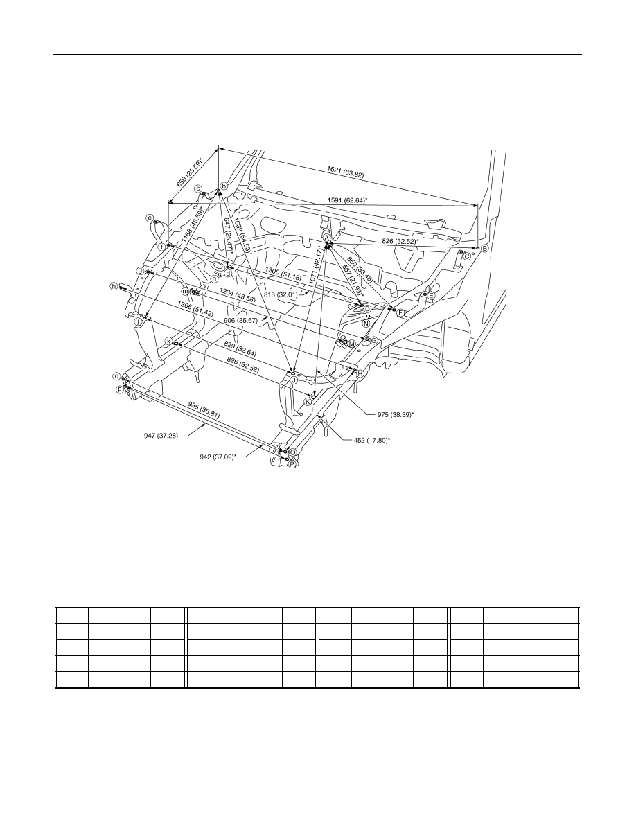
Engine Compartment
INFOID:0000000005248954
Measurement
Dimensions marked with
″
*
″
indicate symmetrically identical dimensions on both the right and left hand of the
vehicle.
E
Trans control reinforcement
Hole 12
×
14 (0.47
×
0.55)
F
Rear seat crossmember reinforcement
Hole
φ
5 (0.20)
Points
Portion
Marks
1.
Vehicle center
2.
Front axle center
3.
Imaginary base line
JSKIA0073GB
BRM-20
< REMOVAL AND INSTALLATION >
BODY ALIGNMENT
«The others»
Unit: mm (in)
Measurement Points
Unit: mm (in)
JSKIA0661GB
Point
Dimension
Memo
Point
Dimension
Memo
Point
Dimension
Memo
Point
Dimension
Memo
A - C
806 (31.73)*
B - C
178 (7.01)*
B - e
1682 (66.22)*
b - G
1651 (65.00)
A - E
930 (36.61)*
B - c
1601 (63.03)*
B - G
849 (33.43)
C - c
1561 (61.46)
A - G
961 (37.83)
B - d
1318 (51.89)*
b - g
860 (33.86)
E - e
1533 (60.35)
A - g
966 (38.03)
B - E
587 (23.11)*
B - g
1653 (65.08)
N - n
906 (35.67)
BODY ALIGNMENT
BRM-21
< REMOVAL AND INSTALLATION >
C
D
E
F
G
H
I
J
L
M
A
B
BRM
N
O
P
Unit: mm (in)
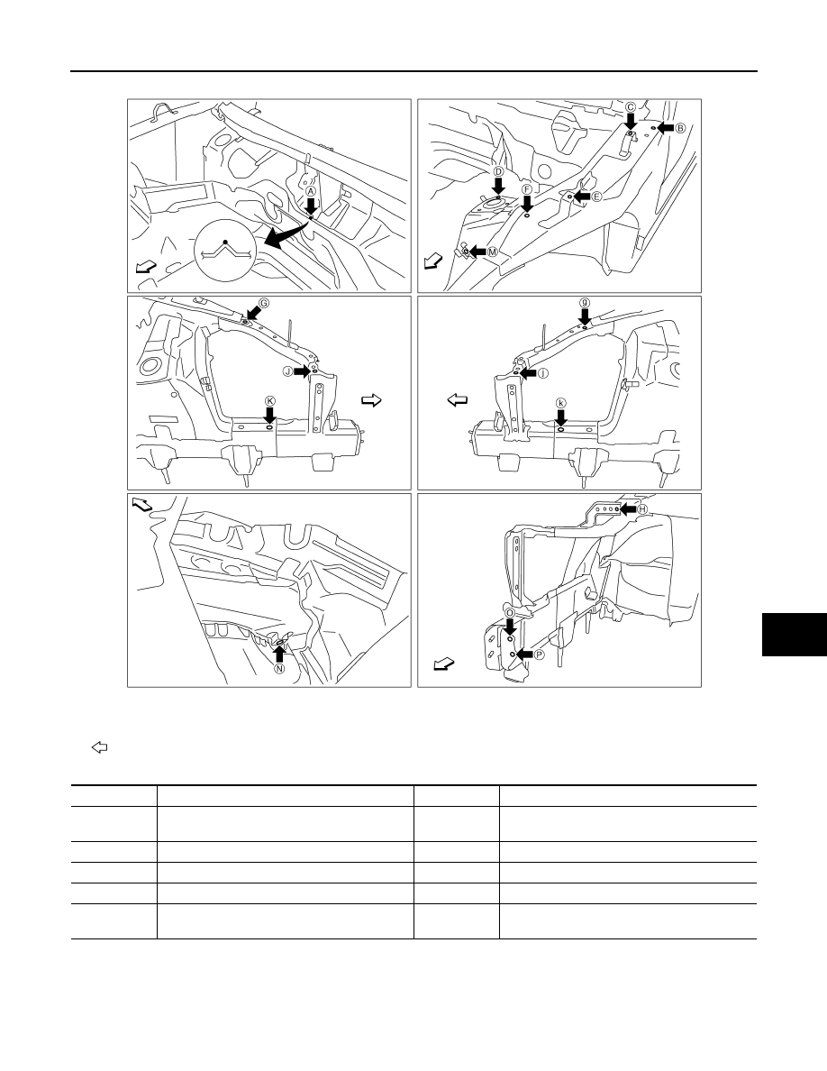
Underbody
INFOID:0000000005248955
Measurement
Dimensions marked with
″
*
″
indicate symmetrically identical dimensions on both the right and left hand of the
vehicle.
: Vehicle front
JSKIA0662ZZ
Point
Material
Point
Material
A
Upper dash positioning mark of center position-
ing mark
G, g
Radiator core support hole center
φ
7 (0.28)
B, b
Hood hinge installing hole center
φ
9 (0.35)
J, j
Radiator core support stay hole center
φ
12 (0.47)
C, c, E, e, H, h
Front fender installing hole center
φ
7 (0.28)
K, k
Front side member hole center
φ
10 (0.39)
D, d
Front strut installing hole center
φ
11 (0.43)
M, m, N, n
Nut holder hole center
φ
16 (0.63)
F, f
Hoodledge reinforcement hole center
φ
12 (0.47)
O, o, P, p
Front bumper reinforcement installing hole center
φ
11 (0.43)
Нет комментариевНе стесняйтесь поделиться с нами вашим ценным мнением.
Текст