Infiniti FX35, FX50 (S51). Manual — part 1172

MAGNET CLUTCH
HAC-85
< DTC/CIRCUIT DIAGNOSIS >
[AUTOMATIC AIR CONDITIONER]
C
D
E
F
G
H
J
K
L
M
A
B
HAC
N
O
P
Is the inspection result normal?
YES
>> GO TO 8.
NO
>> GO TO 6.
6.
CHECK REFRIGERANT PRESSURE SENSOR
WITH CONSULT-III
1.
Start the engine.
2.
Check voltage of refrigerant pressure sensor in “Data monitor”. Refer to
(VQ35HR) or
HAC-121, "VK50VE : Reference Value"
(VK50VE).
WITHOUT CONSULT-III
1.
Start the engine.
2.
Check voltage between ECM harness connector and ground.
VQ35HR
VK50VE
Is the inspection result normal?
YES
>> •
WITH CONSULT-III: GO TO 7.
•
WITHOUT CONSULT-III: Repair harness or connector.
NO
>> Refer to
EC-1127, "Diagnosis Procedure"
(VK50VE).
7.
CHECK ECM INPUT SIGNAL-2
Check blower fan motor switch signal in “Data monitor”. Refer to
HAC-62, "WITHOUT ACCS : CONSULT-III
HAC-67, "WITH ACCS : CONSULT-III Function"
(WITH ACCS).
Is the inspection result normal?
YES
>> GO TO 8.
NO
>> Repair harness or connector.
8.
CHECK CAN COMMUNICATION
Check CAN communication. Refer to
LAN-20, "Trouble Diagnosis Flow Chart"
.
• ECM – IPDM E/R
• ECM – Unified meter and A/C amp.
Is the inspection result normal?
YES
>> Replace ECM.
NO
>> Repair or replace malfunctioning part(s).
(+)
(
−
)
Condition
Voltage
ECM
—
connector
Terminal
M107
105
Ground
A/C switch: ON
(Blower motor operates.)
Approx. 1.0 - 4.0 V
(+)
(
−
)
Condition
Voltage
ECM
—
connector
Terminal
F111
90
Ground
A/C switch: ON
(Blower motor operates.)
Approx. 1.0 - 4.0 V
FAN SWITCH ON
: HEATER FAN SW On
FAN SWITCH OFF
: HEATER FAN SW Off

HAC-86
< DTC/CIRCUIT DIAGNOSIS >
[AUTOMATIC AIR CONDITIONER]
ECV (ELECTRICAL CONTROL VALVE)
ECV (ELECTRICAL CONTROL VALVE)
Description
INFOID:0000000005246273
The ECV (electrical control valve) is installed on the compressor and controls it for emitting appropriate
amount of refrigerant when necessary.
Diagnosis Procedure
INFOID:0000000005246274
1.
CHECK FUSE
Check 10A fuse [No. 3, located in the fuse block (J/B)].
NOTE:
Refer to
PG-158, "Fuse, Connector and Terminal Arrangement"
Is the inspection result normal?
YES
>> GO TO 2.
NO
>> Replace the fuse after repairing the applicable circuit.
2.
CHECK ECV POWER SUPPLY CIRCUIT
1.
Turn the ignition switch OFF.
2.
Disconnect the ECV connector.
3.
Turn the ignition switch ON.
4.
Check voltage between the ECV harness connector and ground.
Is the inspection result normal?
YES
>> GO TO 3.
NO
>> Repair the harnesses or connectors.
3.
CHECK ECV CONTROL SIGNAL
1.
Turn the ignition switch OFF.
2.
Connect the ECV connector.
3.
Perform the self-diagnosis STEP-4 (Code No. 45). Refer to
HAC-57, "WITHOUT ACCS : Diagnosis
(WITHOUT ACCS) or
HAC-62, "WITH ACCS : Diagnosis Description"
(WITH ACCS).
4.
Check output waveform between the unified meter and A/C amp. harness connector and ground with the
oscilloscope.
Is the inspection result normal?
YES
>> Replace the compressor.
NO
>> GO TO 4.
4.
CHECK CONTINUITY BETWEEN ECV AND UNIFIED METER AND A/C AMP.
1.
Turn the ignition switch OFF.
(+)
(
−
)
Voltage
ECV
—
Connector
Terminal
F44
2
Ground
Battery voltage
(+)
(
−
)
Condition
Output waveform
Unified meter and A/C amp.
—
Connector
Terminal
M67
65
Ground
• Ignition switch ON
• Self-diagnosis. STEP-4
(Code No. 45)
Duty ratio: approx. 50 %
SJIA1607E

ECV (ELECTRICAL CONTROL VALVE)
HAC-87
< DTC/CIRCUIT DIAGNOSIS >
[AUTOMATIC AIR CONDITIONER]
C
D
E
F
G
H
J
K
L
M
A
B
HAC
N
O
P
2.
Disconnect the ECV connector.
3.
Disconnect the unified meter and A/C amp. connector.
4.
Check continuity between the ECV harness connector and unified meter and A/C amp. harness connec-
tor.
5.
Check for continuity between the ECV harness connector and ground.
Is the inspection result normal?
YES
>> GO TO 5.
NO
>> Repair the harnesses or connectors.
5.
CHECK ECV
Check continuity between the ECV connector terminals.
Is the inspection result normal?
YES
>> Replace the unified meter and A/C amp.
NO
>> Replace the compressor.
ECV
Unified meter and A/C amp.
Continuity
Connector
Terminal
Connector
Terminal
F44
3
M67
65
Existed
ECV
—
Continuity
Connector
Terminal
F44
3
Ground
Not existed
ECV
Continuity
Terminal
Terminal
2
3
Existed
HAC-88
< DTC/CIRCUIT DIAGNOSIS >
[AUTOMATIC AIR CONDITIONER]
AMBIENT SENSOR
AMBIENT SENSOR
Description
INFOID:0000000005246275
COMPONENT DESCRIPTION
Ambient Sensor
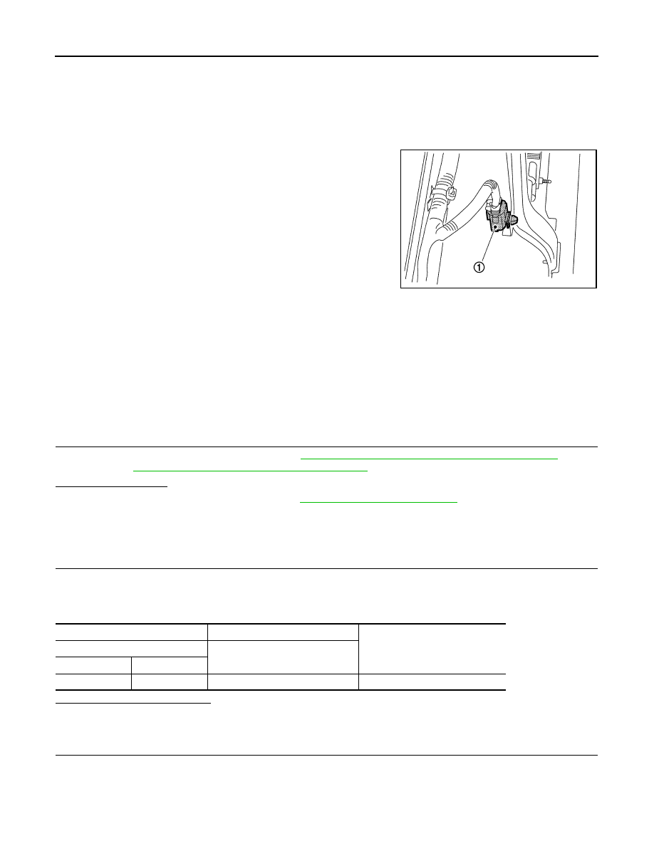
The ambient sensor (1) is attached on hood lock stay assembly. It
detects ambient temperature and converts it into a resistance value
which is then input into the unified meter and A/C amp.
AMBIENT TEMPERATURE INPUT PROCESS
The unified meter and A/C amp. equips a processing circuit for the ambient sensor input. However, when the
temperature detected by the ambient sensor increases quickly, the processing circuit retards the unified meter
and A/C amp. function. It only allows the unified meter and A/C amp. to recognize an ambient temperature
increase of 0.33
°
C (0.6
°
F) per 100 seconds.
As an example, consider stopping for a few minutes after high speed driving. Although the actual ambient tem-
perature has not changed, the temperature detected by the ambient sensor increases. This is because the
heat from the engine compartment can radiate to the front bumper area, location of the ambient sensor.
Component Function Check
INFOID:0000000005246276
1.
PERFORM SELF-DIAGNOSIS
Perform self-diagnosis function STEP-2. Refer to
HAC-57, "WITHOUT ACCS : Diagnosis Description"
(WITH-
OUT ACCS) or
HAC-62, "WITH ACCS : Diagnosis Description"
(WITH ACCS).
21 or
−
21 is displayed.
YES
>> Go to Diagnosis Procedure. Refer to
.
NO
>> INSPECTION END
Diagnosis Procedure
INFOID:0000000005246277
1.
CHECK VOLTAGE BETWEEN AMBIENT SENSOR AND GROUND
1.
Disconnect ambient sensor connector.
2.
Turn ignition switch ON.
3.
Check voltage between ambient sensor harness connector and ground.
Is the inspection result normal?
YES
>> GO TO 2.
NO
>> GO TO 4.
2.
CHECK CIRCUIT CONTINUITY BETWEEN AMBIENT SENSOR AND UNIFIED METER AND A/C AMP.
1.
Turn ignition switch OFF.
2.
Disconnect unified meter and A/C amp. connector.
3.
Check continuity between ambient sensor harness connector and unified meter and A/C amp. harness
connector.
JSIIA1293ZZ
(+)
(
−
)
Voltage
Ambient sensor
—
Connector
Terminal
E76
1
Ground
Approx. 5 V
Нет комментариевНе стесняйтесь поделиться с нами вашим ценным мнением.
Текст