Infiniti FX35, FX50 (S51). Manual — part 1171
BLOWER MOTOR
HAC-81
< DTC/CIRCUIT DIAGNOSIS >
[AUTOMATIC AIR CONDITIONER]
C
D
E
F
G
H
J
K
L
M
A
B
HAC
N
O
P
Is the inspection result normal?
YES
>> GO TO 3.
NO
>> GO TO 6.
3.
CHECK BLOWER MOTOR GROUND CIRCUIT
1.
Turn ignition switch OFF.
2.
Check continuity between blower motor harness connector and ground.
Is the inspection result normal?
YES
>> GO TO 4.
NO
>> Repair harness or connector.
4.
CHECK CIRCUIT CONTINUITY BETWEEN BLOWER MOTOR AND UNIFIED METER AND A/C AMP.
1.
Disconnect unified meter and A/C amp. connector.
2.
Check continuity between blower motor harness connector and unified meter and A/C amp. harness con-
nector.
3.
Check continuity between blower motor harness connector and ground.
Is the inspection result normal?
YES
>> GO TO 5.
NO
>> Repair harness or connector.
5.
CHECK UNIFIED METER AND A/C AMP. OUTPUT SIGNAL
1.
Reconnect blower motor connector and unified meter and A/C amp. connector.
2.
Turn ignition switch ON.
3.
Set MODE switch to VENT position.
(+)
(
−
)
Voltage
Blower motor
—
Connector
Terminal
M109
1
Ground
Battery voltage
Blower motor
—
Continuity
Connector
Terminal
M109
3
Ground
Existed
Blower motor
Unified meter and A/C amp.
Continuity
Connector
Terminal
Connector
Terminal
M109
2
M66
38
Existed
Blower motor
—
Continuity
Connector
Terminal
M109
2
ground
Not existed
HAC-82
< DTC/CIRCUIT DIAGNOSIS >
[AUTOMATIC AIR CONDITIONER]
BLOWER MOTOR
4.
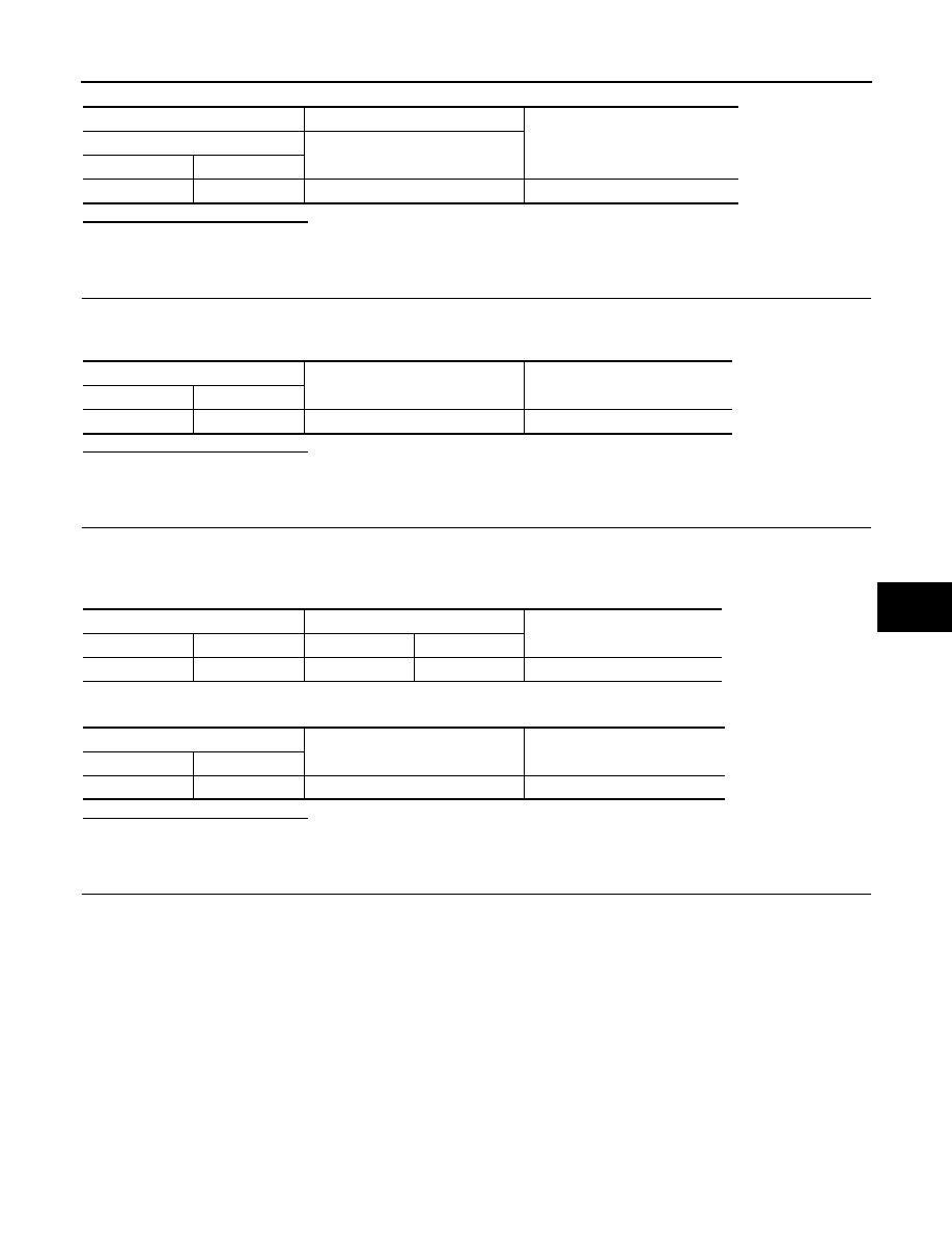
Change fan speed from Lo to Hi, and check duty ratios between blower motor harness connector and
ground by using an oscilloscope. Normal terminal 2 drive signal duty ratios are shown in the table below.
Is the inspection result normal?
YES
>> Replace blower motor after confirming the fan air flow does not change.
NO
>> Replace unified meter and A/C amp.
6.
CHECK POWER VOLTAGE OF BLOWER RELAY
1.
Turn ignition switch OFF.
2.
Remove blower relay. Refer to
PG-156, "Fuse, Connector and Terminal Arrangement"
3.
Turn ignition switch ON.
4.
Check the voltage between blower relay fuse block terminals and ground. Refer to
for relay terminal assignment.
Is the inspection result normal?
YES
>> GO TO 7.
NO
>> Check ignition power supply circuit. Refer to
PG-81, "Wiring Diagram - IGNITION POWER SUP-
7.
CHECK BLOWER RELAY
1.
Turn ignition switch OFF.
2.
Install blower relay. Refer to
PG-156, "Fuse, Connector and Terminal Arrangement"
3.
Check operation sound of the blower relay after switching ignition switch ON.
Is the inspection result normal?
YES
>> GO TO 8.
NO
>> Replace blower relay.
8.
CHECK FUSE
Check fuse 15A [Nos. 21 and 22, located in the fuse block (J/B)]. Refer to
PG-156, "Fuse, Connector and Ter-
.
Is the inspection result normal?
YES
>> Repair harness or connector.
NO
>> Be sure to eliminate cause of malfunction before installing new fuse.
JSIIA0068GB
(+)
(
−
)
Voltage
Blower relay
—
1
Ground
Battery voltage
3
BLOWER MOTOR
HAC-83
< DTC/CIRCUIT DIAGNOSIS >
[AUTOMATIC AIR CONDITIONER]
C
D
E
F
G
H
J
K
L
M
A
B
HAC
N
O
P
Component Inspection
INFOID:0000000005246269
1.
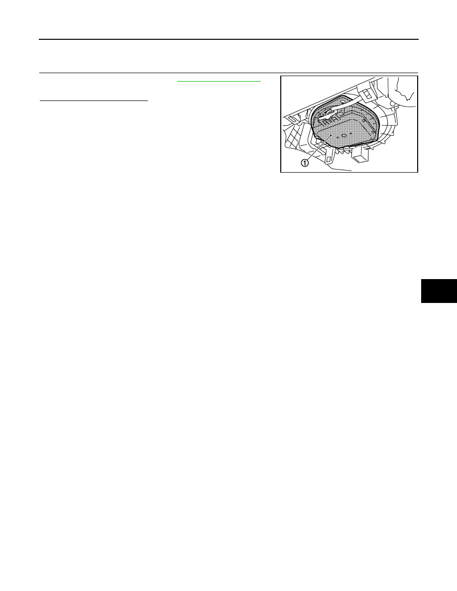
CHECK BLOWER MOTOR
1.
Remove blower motor (1). Refer to
2.
Confirm smooth rotation of the blower motor.
Is the inspection result normal?
YES
>> INSPECTION END
NO
>> Replace blower motor.
JSIIA1074ZZ
HAC-84
< DTC/CIRCUIT DIAGNOSIS >
[AUTOMATIC AIR CONDITIONER]
MAGNET CLUTCH
MAGNET CLUTCH
Description
INFOID:0000000005246270
Magnet clutch drives a compressor, by a signal of IPDM E/R.
Component Function Check
INFOID:0000000005246271
1.
CONFIRM SYMPTOM BY PERFORMING THE FOLLOWING OPERATIONAL CHECK
1.
Press AUTO switch.
2.
Display should indicate AUTO. Confirm that the magnet clutch engages (sound or visual inspection). (Dis-
charge air and blower speed depend on ambient, in-vehicle and set temperatures.)
Does the magnet clutch operate?
YES
>> INSPECTION END
NO
>> Go to Diagnosis Procedure. Refer to
.
Diagnosis Procedure
INFOID:0000000005246272
1.
PERFORM SELF-DIAGNOSIS
Perform self-diagnosis function. Refer to
HAC-57, "WITHOUT ACCS : Diagnosis Description"
(WITHOUT
ACCS) or
HAC-62, "WITH ACCS : Diagnosis Description"
Is the inspection result normal?
YES
>> INSPECTION END
NO
>> GO TO 2.
2.
PERFORM IPDM E/R AUTO ACTIVE TEST
Perform IPDM E/R auto active test. Refer to
PCS-11, "Diagnosis Description"
Does the magnet clutch operate?
YES-1 >>
WITH CONSULT-III: GO TO 5.
YES-2 >>
WITHOUT CONSULT-III: GO TO 6.
NO
>> Check 10A fuse (No. 49, located in IPDM E/R), and GO TO 3.
3.
CHECK CIRCUIT CONTINUITY BETWEEN IPDM E/R AND COMPRESSOR
1.
Turn ignition switch OFF.
2.
Disconnect IPDM E/R connector and compressor connector.
3.
Check continuity between IPDM E/R harness connector and compressor harness connector.
Is the inspection result normal?
YES
>> GO TO 4.
NO
>> Repair harness or connector.
4.
CHECK MAGNET CLUTCH CIRCUIT
Check for operation sound when applying battery voltage direct current to terminal.
Is the inspection result normal?
YES
>> Replace IPDM E/R.
NO
>> Replace compressor.
5.
CHECK ECM INPUT SIGNAL-1
Check A/C switch signal in “Data monitor”. Refer to
HAC-62, "WITHOUT ACCS : CONSULT-III Function"
(WITHOUT ACCS) or
HAC-67, "WITH ACCS : CONSULT-III Function"
(WITH ACCS).
IPDM E/R
Compressor
Continuity
Connector
Terminal
Connector
Terminal
E7
48
F43
1
Existed
A/C SWITCH ON
: AIR COND SIG On
A/C SWITCH OFF
: AIR COND SIG Off
Нет комментариевНе стесняйтесь поделиться с нами вашим ценным мнением.
Текст