Infiniti FX35, FX50 (S51). Manual — part 1552
REAR WHEEL HUB AND HOUSING
RAX-5
< PERIODIC MAINTENANCE >
C
E
F
G
H
I
J
K
L
M
A
B
RAX
N
O
P
PERIODIC MAINTENANCE
REAR WHEEL HUB AND HOUSING
Inspection
INFOID:0000000005249006
MOUNTING INSPECTION
Make sure the mounting conditions (looseness, back lash) of each component and component conditions
(wear, damage) are normal.
WHEEL BEARING INSPECTION
• Move wheel hub and bearing assembly in the axial direction by hand. Make sure there is no looseness of
wheel bearing.
• Rotate wheel hub, and make sure there is no unusual noise or other irregular conditions. If there is any of
irregular conditions, replace wheel hub and bearing assembly.
Axial end play
: Refer to
RAX-6
< PERIODIC MAINTENANCE >
REAR DRIVE SHAFT
REAR DRIVE SHAFT
Inspection
INFOID:0000000005249007
• Check drive shaft mounting point and joint for looseness and other damage.
• Check boot for cracks and other damage.
CAUTION:
Replace entire drive shaft assembly when noise or vibration occurs from drive shaft.
REAR WHEEL HUB AND HOUSING
RAX-7
< REMOVAL AND INSTALLATION >
C
E
F
G
H
I
J
K
L
M
A
B
RAX
N
O
P
REMOVAL AND INSTALLATION
REAR WHEEL HUB AND HOUSING
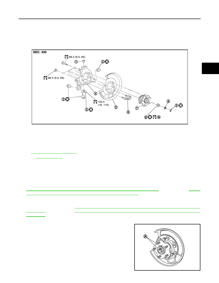
Exploded View
INFOID:0000000005249008
Removal and Installation
INFOID:0000000005249009
REMOVAL
1.
Remove tire with power tool.
2.
Remove caliper assembly. Hang caliper assembly in a place where it will not interfere with work. Refer to
BR-56, "BRAKE CALIPER ASSEMBLY (1 PISTON TYPE) : Exploded View"
(1 piston type),
"BRAKE CALIPER ASSEMBLY (2 PISTON TYPE) : Exploded View"
CAUTION:
Never depress brake pedal while caliper assembly is removed.
3.
Remove disc rotor. Refer to
BR-57, "BRAKE CALIPER ASSEMBLY (1 PISTON TYPE) : Removal and
(1 piston type),
BR-61, "BRAKE CALIPER ASSEMBLY (2 PISTON TYPE) : Removal and
(2 piston type).
4.
Remove cotter pin and adjusting cap, then loosen wheel hub lock nut with power tool.
5.
Put matching mark (A) on drive shaft and wheel hub and bearing
assembly.
CAUTION:
Use paint or similar substance for matching marks. Never
scratch the surface.
1.
Ball seat
2.
Bushing
3.
Cotter pin
4.
Axle housing
5.
Back plate
6.
Anchor block
7.
Wheel hub and bearing assembly
8.
Wheel hub lock nut
9.
Adjusting cap
A.
Tightening must be done following
the installation procedure. Refer to
RAX-7, "Removal and Installation"
.
Refer to
JPDIG0157GB
JPDIG0121ZZ
RAX-8
< REMOVAL AND INSTALLATION >
REAR WHEEL HUB AND HOUSING
6.
Patch wheel hub lock nut with a piece of wood. Hammer the
wood to disengage wheel hub and bearing assembly from drive
shaft.
CAUTION:
• Never place drive shaft joint at an extreme angle. Also be
careful not to overextend slide joint.
• Never allow drive shaft to hang down without support for
counterpart such as joint sub-assembly, and other parts.
NOTE:
Use a suitable puller, if wheel hub and bearing assembly and
drive shaft cannot be separated even after performing the above
procedure.
7.
Remove wheel hub lock nut.
8.
Remove parking brake shoe and parking brake cable from back plate. Refer to
and
9.
Remove stabilizer connecting rod (upper side) with power tool. Refer to
.
10. Remove coil spring. Refer to
11. Set suitable jack under axle housing.
12. Remove radius rod. Refer to
13. Remove shock absorber (lower side) with power tool. Refer to
14. Separate suspension arm from axle housing so as not to damage ball joint boot using ball joint remover
(commercial service tool), and then remove axle housing from the vehicle.
CAUTION:
• Temporarily tighten nuts to prevent damage to threads and to prevent the ball joint remover from
coming off.
• Never place drive shaft joint at an extreme angle. Also be careful not to overextend slide joint.
• Never allow drive shaft to hang down without support for counterpart such as joint sub-assem-
bly, and other parts.
15. Remove front lower link (axle housing side). Refer to
.
16. Remove rear lower link (axle housing side). Refer to
.
17. Remove wheel hub and bearing assembly.
18. Remove anchor block mounting nuts, and then remove anchor block and back plate from axle housing.
INSTALLATION
Note the following, and install in the reverse order of removal.
• Clean the matching surface of wheel hub lock nut and wheel hub and bearing assembly.
CAUTION:
Never apply lubricating oil to these matching surface.
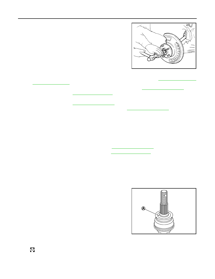
• Clean the matching surface of drive shaft and wheel hub and bear-
ing assembly. And then apply paste [service parts (440037S000)]
to surface (A) of joint sub-assembly of drive shaft.
CAUTION:
Apply paste to cover entire flat surface of joint sub-assembly
of drive shaft.
• Use the following torque range for tightening the wheel hub lock nut.
CAUTION:
• Since the drive shaft is assembled by press-fitting, use the tightening torque range for the wheel
hub lock nut.
JPDIG0070ZZ
Amount paste
: 1.0 – 3.0 g (0.04 – 0.10 oz)
JPDIG0122ZZ
: 180 N·m (18.4 kg-m, 133 ft-lb) – 185 N·m (18.8 kg-m, 136 ft-lb)
Нет комментариевНе стесняйтесь поделиться с нами вашим ценным мнением.
Текст