Infiniti FX35, FX50 (S51). Manual — part 1972

FRONT WIPER DOES NOT OPERATE
WW-111
< SYMPTOM DIAGNOSIS >
C
D
E
F
G
H
I
J
K
M
A
B
WW
N
O
P
FRONT WIPER DOES NOT OPERATE
Description
INFOID:0000000005234784
The front wiper does not operate under any operation conditions.
Diagnosis Procedure
INFOID:0000000005234785
1.
CHECK WIPER RELAY OPERATION
IPDM E/R AUTO ACTIVE TEST
1.
Start IPDM E/R auto active test. Refer to
PCS-11, "Diagnosis Description"
2.
Check that the front wiper operates at the LO/HI operation.
CONSULT-III ACTIVE TEST
1.
Select “FRONT WIPER” of IPDM E/R active test item.
2.
With operating the test item, check front wiper operation.
Is front wiper operation normally?
YES
>> GO TO 5.
NO
>> GO TO 2.
2.
CHECK FRONT WIPER MOTOR FUSE
1.
Turn the ignition switch OFF.
2.
Check that the front wiper motor 30A fuse (#60) is not fusing.
Is the fuse fusing?
YES
>> Replace the fuse after repairing the applicable circuit.
NO
>> GO TO 3.
3.
CHECK FRONT WIPER MOTOR GROUND OPEN CIRCUIT
1.
Disconnect front wiper motor connector.
2.
Check continuity between front wiper motor harness connector and ground.
Does continuity exist?
YES
>> GO TO 4.
NO
>> Repair the harness or connector.
4.
CHECK FRONT WIPER MOTOR OUTPUT VOLTAGE
CONSULT-III ACTIVE TEST
1.
Turn the ignition switch ON.
2.
Select “FRONT WIPER” of IPDM E/R active test item.
3.
With operating the test item, check voltage between IPDM E/R harness connector and ground.
Lo
: Front wiper LO operation
Hi
: Front wiper HI operation
Off
: Stop the front wiper.
Front wiper motor
Ground
Continuity
Connector
Terminal
E42
2
Existed

WW-112
< SYMPTOM DIAGNOSIS >
FRONT WIPER DOES NOT OPERATE
Is the measurement value normal?
YES
>> Replace front wiper motor.
NO
>> Replace IPDM E/R.
5.
CHECK FRONT WIPER REQUEST SIGNAL INPUT
CONSULT-III DATA MONITOR
1.
Select “FR WIP REQ” of IPDM E/R data monitor item.
2.
Switch the front wiper switch to HI and LO.
3.
With operating the front wiper switch, check the status of “FR WIP REQ”.
Is the status of item normal?
YES
>> Replace IPDM E/R.
NO
>> GO TO 6.
6.
CHECK COMBINATION SWITCH
Perform the inspection of the combination switch. Refer to
Is combination switch normal?
YES
>> Replace BCM. Refer to
NO
>> Repair or replace the applicable parts.
Terminals
Test item
Voltage (Approx.)
(+)
(
−
)
IPDM E/R
Ground
FRONT WIPER
Connector
Terminal
E5
4
Lo
Battery voltage
Off
0 V
5
Hi
Battery voltage
Off
0 V
Monitor item
Condition
Monitor status
FR WIP REQ
Front wiper switch HI
On
Hi
Off
Stop
Front wiper switch LO
On
Low
Off
Stop
PRECAUTIONS
WW-113
< PRECAUTION >
C
D
E
F
G
H
I
J
K
M
A
B
WW
N
O
P
PRECAUTION
PRECAUTIONS
Precaution for Supplemental Restraint System (SRS) "AIR BAG" and "SEAT BELT
PRE-TENSIONER"
INFOID:0000000005234786
The Supplemental Restraint System such as “AIR BAG” and “SEAT BELT PRE-TENSIONER”, used along
with a front seat belt, helps to reduce the risk or severity of injury to the driver and front passenger for certain
types of collision. This system includes seat belt switch inputs and dual stage front air bag modules. The SRS
system uses the seat belt switches to determine the front air bag deployment, and may only deploy one front
air bag, depending on the severity of a collision and whether the front occupants are belted or unbelted.
Information necessary to service the system safely is included in the “SRS AIR BAG” and “SEAT BELT” of this
Service Manual.
WARNING:
• To avoid rendering the SRS inoperative, which could increase the risk of personal injury or death in
the event of a collision which would result in air bag inflation, all maintenance must be performed by
an authorized NISSAN/INFINITI dealer.
• Improper maintenance, including incorrect removal and installation of the SRS, can lead to personal
injury caused by unintentional activation of the system. For removal of Spiral Cable and Air Bag
Module, see the “SRS AIR BAG”.
• Do not use electrical test equipment on any circuit related to the SRS unless instructed to in this
Service Manual. SRS wiring harnesses can be identified by yellow and/or orange harnesses or har-
ness connectors.
PRECAUTIONS WHEN USING POWER TOOLS (AIR OR ELECTRIC) AND HAMMERS
WARNING:
• When working near the Air Bag Diagnosis Sensor Unit or other Air Bag System sensors with the
ignition ON or engine running, DO NOT use air or electric power tools or strike near the sensor(s)
with a hammer. Heavy vibration could activate the sensor(s) and deploy the air bag(s), possibly
causing serious injury.
• When using air or electric power tools or hammers, always switch the ignition OFF, disconnect the
battery, and wait at least 3 minutes before performing any service.
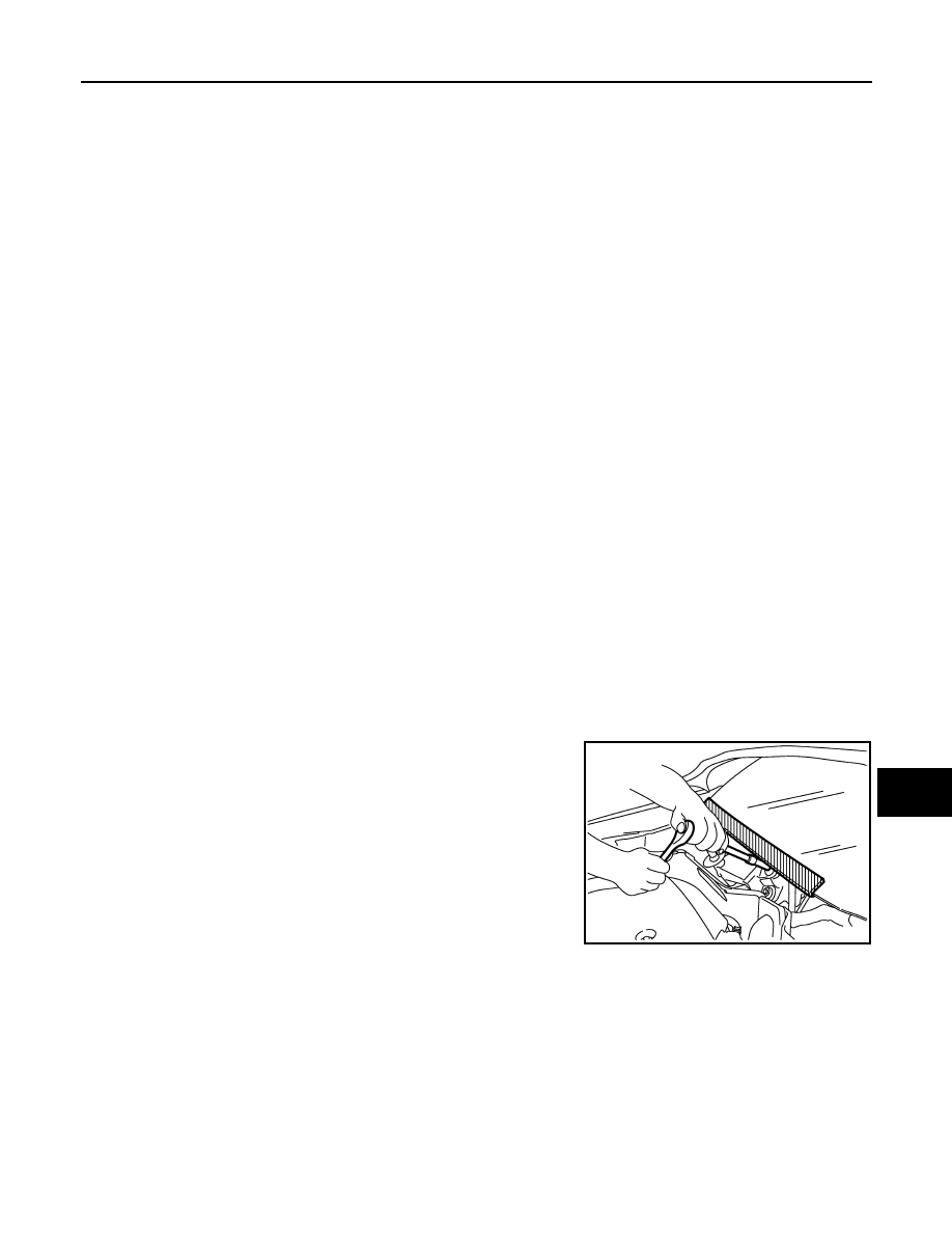
Precaution for Procedure without Cowl Top Cover
INFOID:0000000005234787
When performing the procedure after removing cowl top cover, cover
the lower end of windshield with urethane, etc.
PIIB3706J
WW-114
< REMOVAL AND INSTALLATION >
WASHER TANK
REMOVAL AND INSTALLATION
WASHER TANK
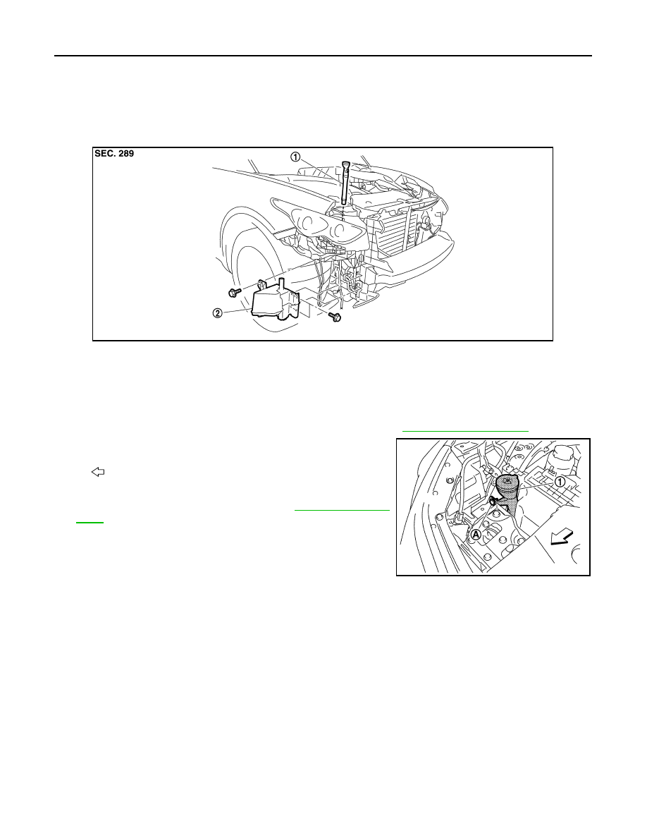
Exploded View
INFOID:0000000005234788
Removal and Installation
INFOID:0000000005234789
REMOVAL
1.
Remove the engine room cover RH (for VK50VE engine). Refer to
2.
Remove the clip (A).
3.
Pull out the washer tank inlet (1) from the washer tank.
4.
Remove the front bumper fascia. Refer to
.
5.
Disconnect the washer pump connector.
6.
Disconnect the washer level switch connector.
7.
Disconnect the front washer tube and rear washer tube.
8.
Remove the washer tank mounting bolts.
9.
Remove the washer tank from the vehicle.
INSTALLATION
Install in the reverse order of removal.
CAUTION:
Add water up to the top of the washer tank inlet after installing. Check that there is no leakage.
1.
Washer tank inlet
2.
Washer tank
JPLIA1225ZZ
: Vehicle front
JPLIA1226ZZ
Нет комментариевНе стесняйтесь поделиться с нами вашим ценным мнением.
Текст