Infiniti FX35, FX50 (S51). Manual — part 408
CCS-452
< SYSTEM DESCRIPTION >
[LDW & LDP]
LANE DEPARTURE WARNING (LDW) SYSTEM
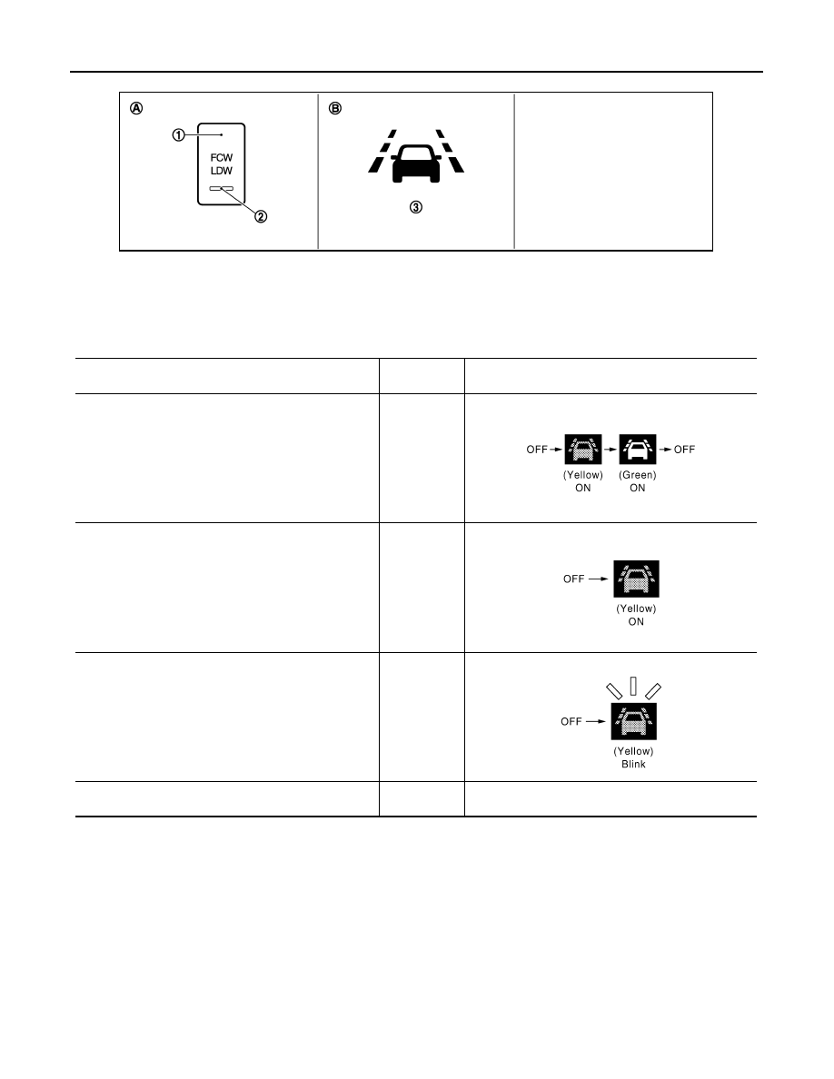
Bulb Check Action and Fail-safe Indication
NOTE:
*: The FCW system operates.
LDW INITIAL STATE CHANGE
CAUTION:
Never change LDW initial state “ON”
⇒
“OFF” without the consent of the customer.
LDW initial state can be changed.
• LDW initial ON* - LDW function is automatically turned ON, when the ignition switch OFF
⇒
ON.
• LDW initial OFF - LDW function is still OFF when the ignition switch OFF
⇒
ON.
*: Factory setting
How to change LDW initial state
1.
Turn ignition switch ON.
2.
Switch LDW and LDP functions to OFF.
1.
LDW switch
(Shared with the FCW system)
2.
LDW ON indicator
(Shared with the FCW system)
3.
Lane departure warning lamp
(Yellow)
A.
On the instrument driver lower panel
B.
On the combination meter
JPOIA0175ZZ
Vehicle condition/ Driver's operation
LDW ON indi-
cator
Indication on the combination meter
Ignition switch:
OFF
⇒
ON
2 sec. ON
When DTC is detected
(Except “C1B01” and “C1B03”)
ON
*
Camera aiming is not completed
(“C1B01” is detected)
ON
*
Temporary disabled status at high temperature
(“C1B03” is detected)
Blink
*
OFF
JPOIA0017GB
JPOIA0019GB
JPOIA0020GB

CCS
LANE DEPARTURE WARNING (LDW) SYSTEM
CCS-453
< SYSTEM DESCRIPTION >
[LDW & LDP]
C
D
E
F
G
H
I
J
K
L
M
B
N
P
A
3.
Push and hold LDW switch for more than 4 seconds.
4.
Buzzer sounds and blinking of the lane departure warning lamp informs that the LDW initial state change
is completed.
LDW SYSTEM CONTROL DESCRIPTION
• LDW system is controlled by lane camera unit.
• Lane camera unit monitors lane markers of the traveling lane.
• Combination meter turns the lane departure warning lamp ON/OFF according to the signal from the lane
camera unit via CAN communication (through unified meter and A/C amp.).
• When the lane camera unit judges vehicle deviation from the traveling lane, it controls following actions to
alert the driver.
- Requests the lane departure warning lamp activation to combination meter.
- Controls the lane departure warning buzzer.
LDW OPERATING CONDITION
• LDW ON indicator: ON
NOTE:
LDP ON indicator lamp is OFF.
• Vehicle speed: approximately 72 km/h (45 MPH) or more
NOTE:
For details of LDW system operating conditions, refer to normal operating condition
.
SIGNAL INPUT/OUTPUT BY CAN COMMUNICATION
Lane camera unit receives signals via CAN communication. It also detects vehicle conditions that are neces-
sary for LDW control.
Input
Output
Vehicle speed
(Approx.)
[km/h (MPH)]
Vehicle condition/ Driver's op-
eration
Action
LDW ON
indictor
Indication on the combination
meter
Buzzer
Less than 64
(40)
Close to lane marker
No action
ON
OFF
—
72 (45) or
more
Close to lane marker
Warning
• Buzzer sounds
• Warning lamp
blinks
ON
Short continu-
ous beeps
• Close to lane marker
• Turn signal ON (Deviate
side)
No action
ON
OFF
—
JPOIA0018GB
Reception Unit
Signal Name
Transmission Unit
Description
Lane camera unit
Vehicle speed signal
ABS actuator and elec-
tric unit (control unit)
Detects the vehicle speed
Turn indicator signal
BCM
Detects operation of turn signals
LDW ON signal
ICC sensor integrated
unit
Detects the LDW ON status
Combination meter
(through unified meter
and A/C amp.)
Lane departure warning lamp
signal
Lane camera unit
Turns the lane departure warning lamp ON/OFF
according to the request
ICC sensor integrated
unit
(through ABS actua-
tor and electric unit
(control unit))
LDW switch signal
Lane camera unit
Detects the LDW switch status
CCS-454
< SYSTEM DESCRIPTION >
[LDW & LDP]
LANE DEPARTURE WARNING (LDW) SYSTEM
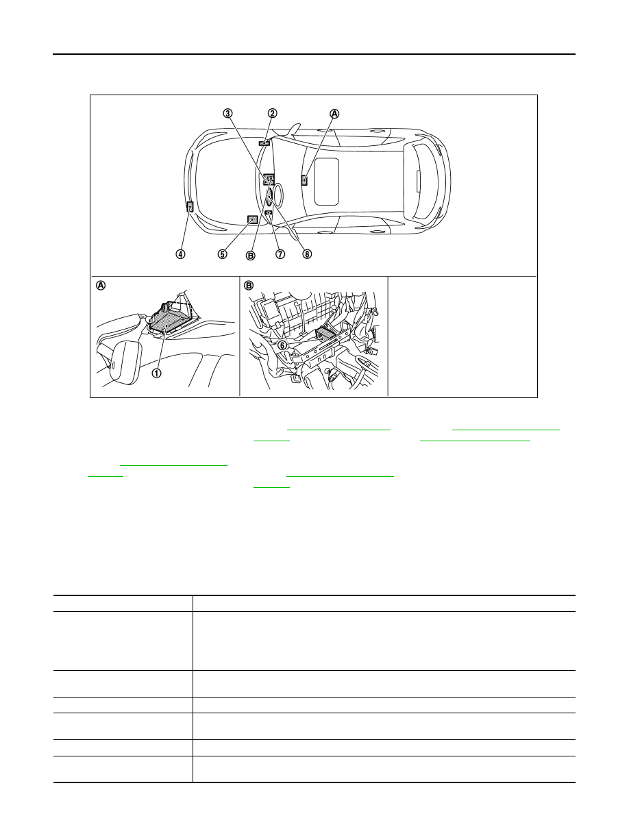
Component Parts Location
INFOID:0000000005502066
Component Description
INFOID:0000000005502067
1.
Lane camera unit
2.
BCM
Refer to
3.
Unified meter and A/C amp.
Refer to
.
4.
ICC sensor integrated unit
Refer to
.
5.
ABS actuator and electric unit (con-
trol unit)
Refer to
6.
Lane departure warning buzzer
7.
LDW switch
8.
Lane departure warning lamp (Yel-
low)
(On the combination meter)
A.
Front of the map lamp
B.
Behind the console finisher assem-
bly
JSOIA0158ZZ
Component
Description
Lane camera unit
• Detects the lane marker by the built-in camera.
• Judges the lane departure depending on the lane detection result and each signals.
• Controls the lane departure warning buzzer, lane departure warning lamp and LDW ON indicator.
• Transmits LDW switch signal to ABS actuator and electric unit (control unit) via CAN communi-
cation.
ABS actuator and electric unit
(control unit)
• Transmits vehicle speed signal to lane camera unit via CAN communication.
• Transmits LDW switch signal to ICC sensor integrated unit via CAN communication.
LDW switch
Inputs the switch signal to lane camera unit.
LDW ON indicator
(On the LDW ON switch)
Indicates LDW system status.
Lane departure warning buzzer
Gives a warning according to the direction from lane camera unit.
Combination meter
Turns the lane departure warning lamp and LDP ON indicator lamp ON/OFF according to the sig-
nals from the lane camera unit via CAN communication (through unified meter and A/C amp.).

CCS
LANE DEPARTURE WARNING (LDW) SYSTEM
CCS-455
< SYSTEM DESCRIPTION >
[LDW & LDP]
C
D
E
F
G
H
I
J
K
L
M
B
N
P
A
Lane departure warning lamp
(Yellow)
• Blinks when LDW is functioning to alert the driver.
• Stays ON when LDW system is malfunctioning.
BCM
Transmits turn indicator signal to lane camera unit via CAN communication.
ICC sensor integrated unit
Transmits an LDW ON signal to the lane camera unit when receiving an LDW switch signal from
the ABS actuator and electric unit (control unit).
Component
Description
Нет комментариевНе стесняйтесь поделиться с нами вашим ценным мнением.
Текст