Infiniti FX35, FX50 (S51). Manual — part 407
CCS-448
< BASIC INSPECTION >
[LDW & LDP]
INSPECTION AND ADJUSTMENT
1.
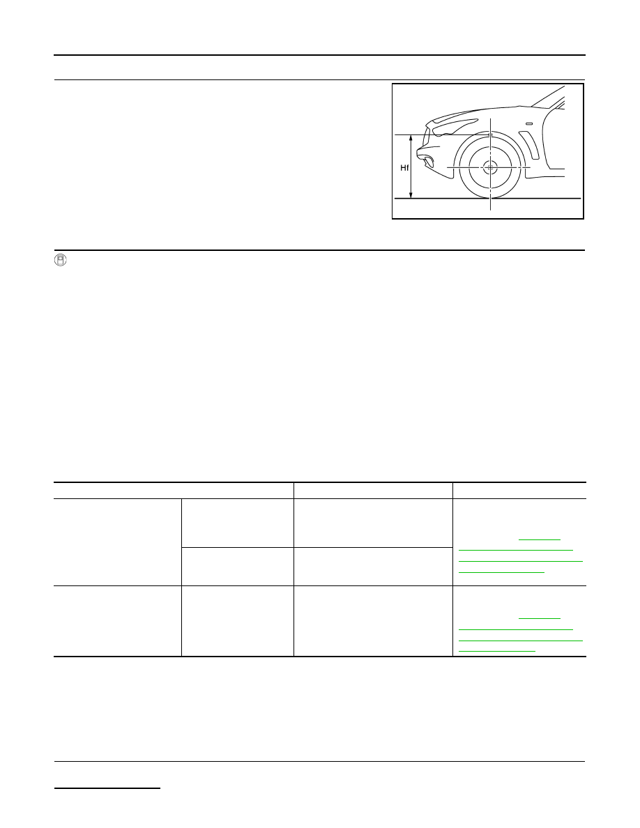
CHECK VEHICLE HEIGHT
Measure the wheelarch height. Calculate “Dh”.
NOTE:
“Dh” may be calculated as a minus value.
>> GO TO 2.
2.
CAMERA AIMING ADJUSTMENT
CONSULT-III WORK SUPPORT
CAUTION:
Operate CONSULT-III outside the vehicle, and close all the doors. (To retain vehicle attitude appropri-
ately)
1.
Select “Work Support” on “LANE CAMERA” with CONSULT-III.
2.
Select “AUTO AIM”.
3.
Confirm the following items;
-
The target should be accurately placed.
-
The vehicle should be stopped.
4.
Select “Start” to perform camera aiming.
CAUTION:
Never select “Start” when the target is not accurately placed.
5.
Input “Dh”, and then select “Start”.
CAUTION:
Never change “Ht” and “Dt”.
6.
Confirm the displayed item.
-
“Normally Completed”: Select “Completion”.
-
“SUSPENSION” or “ABNORMALLY COMPLETED”: Perform the following services.
NOTE:
Replace camera unit if “SUSPENSION” is repeatedly indicated during the above two services are performed.
7.
Confirm that “Normally Completed” is displayed and then select “End” to close the aiming adjustment pro-
cedure.
>> GO TO 3.
3.
PERFORM SELF-DIAGNOSIS
Perform self-diagnosis of lane camera unit with CONSULT-III.
Is any DTC detected?
Dh [mm] = (Hfl + Hfr)
÷
2
−
831
where,
Hfl: Front left wheelarch height [mm]
Hfr: Front right wheelarch height [mm]
JPOIA0174ZZ
Displayed item
Possible cause
Service procedure
SUSPENSION
00H Routine not activated
• A target is not-yet-placed.
(The lane camera unit cannot detect
a target.)
• Lane camera unit malfunction.
Position the target appropriately
again. Perform the aiming
again. Refer to
"CAMERA AIMING ADJUST-
MENT : Special Repair Require-
ment (Target Setting)"
10H Writing error
• Temporary malfunction in internal
processing of the lane camera unit.
• Lane camera unit malfunction.
ABNORMALLY COMPLETED
—
• The position of the target is not cor-
rect.
• The position of the lane camera unit
is not correct.
• Inappropriate work environment.
• Inappropriate vehicle condition.
Position the target appropriately
again. Perform the aiming
again. Refer to
"CAMERA AIMING ADJUST-
MENT : Special Repair Require-
ment (Preparation)"

CCS
INSPECTION AND ADJUSTMENT
CCS-449
< BASIC INSPECTION >
[LDW & LDP]
C
D
E
F
G
H
I
J
K
L
M
B
N
P
A
YES
>> Perform diagnosis on the detected DTC and repair or replace the applicable item. Refer to
.
NO
>> GO TO 4.
4.
ACTION TEST
Test the LDW/LDP system operation by action test. Refer to
.
>> WORK END
CAMERA AIMING ADJUSTMENT : Special Repair Requirement (Target Mark Sample)
INFOID:0000000005502063
NOTE:

CCS-450
< BASIC INSPECTION >
[LDW & LDP]
INSPECTION AND ADJUSTMENT
Print this illustration so that the diameter of the circle is 200 mm (7.87 in).
PGIA0105J
CCS
LANE DEPARTURE WARNING (LDW) SYSTEM
CCS-451
< SYSTEM DESCRIPTION >
[LDW & LDP]
C
D
E
F
G
H
I
J
K
L
M
B
N
P
A
SYSTEM DESCRIPTION
LANE DEPARTURE WARNING (LDW) SYSTEM
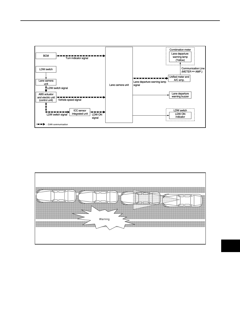
System Diagram
INFOID:0000000005502064
System Description
INFOID:0000000005502065
OUTLINE
• Lane Departure Warning (LDW) system provides a lane departure warning function when the vehicle is
driven at speeds of approximately 72 km/h (45 MPH) or more.
• When the vehicle approaches either the left or the right side of the traveling lane, a warning will sound and
the lane departure warning lamp (yellow) on the combination meter will blink to alert the driver.
• The warning function will stop when the vehicle returns inside of the lane markers.
BASIC OPERATIONS
Switches And Indicator/Warning Lamps
JPOIA0287GB
JPOIA0014GB
Нет комментариевНе стесняйтесь поделиться с нами вашим ценным мнением.
Текст