Infiniti FX35, FX50 (S51). Manual — part 96
AV
PRECAUTIONS
AV-157
< PRECAUTION >
[NAVIGATION (SINGLE MONITOR)]
C
D
E
F
G
H
I
J
K
L
M
B
A
O
P
PRECAUTION
PRECAUTIONS
Precaution for Supplemental Restraint System (SRS) "AIR BAG" and "SEAT BELT
PRE-TENSIONER"
INFOID:0000000005475449
The Supplemental Restraint System such as “AIR BAG” and “SEAT BELT PRE-TENSIONER”, used along
with a front seat belt, helps to reduce the risk or severity of injury to the driver and front passenger for certain
types of collision. This system includes seat belt switch inputs and dual stage front air bag modules. The SRS
system uses the seat belt switches to determine the front air bag deployment, and may only deploy one front
air bag, depending on the severity of a collision and whether the front occupants are belted or unbelted.
Information necessary to service the system safely is included in the “SRS AIR BAG” and “SEAT BELT” of this
Service Manual.
WARNING:
• To avoid rendering the SRS inoperative, which could increase the risk of personal injury or death in
the event of a collision which would result in air bag inflation, all maintenance must be performed by
an authorized NISSAN/INFINITI dealer.
• Improper maintenance, including incorrect removal and installation of the SRS, can lead to personal
injury caused by unintentional activation of the system. For removal of Spiral Cable and Air Bag
Module, see the “SRS AIR BAG”.
• Do not use electrical test equipment on any circuit related to the SRS unless instructed to in this
Service Manual. SRS wiring harnesses can be identified by yellow and/or orange harnesses or har-
ness connectors.
PRECAUTIONS WHEN USING POWER TOOLS (AIR OR ELECTRIC) AND HAMMERS
WARNING:
• When working near the Air Bag Diagnosis Sensor Unit or other Air Bag System sensors with the
ignition ON or engine running, DO NOT use air or electric power tools or strike near the sensor(s)
with a hammer. Heavy vibration could activate the sensor(s) and deploy the air bag(s), possibly
causing serious injury.
• When using air or electric power tools or hammers, always switch the ignition OFF, disconnect the
battery, and wait at least 3 minutes before performing any service.
Precaution for Trouble Diagnosis
INFOID:0000000005475450
AV COMMUNICATION SYSTEM
• Do not apply voltage of 7.0 V or higher to the measurement terminals.
• Use the tester with its open terminal voltage being 7.0 V or less.
• Be sure to turn ignition switch OFF and disconnect the battery cable from the negative terminal before
checking the circuit.
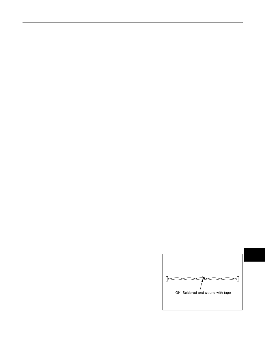
Precaution for Harness Repair
INFOID:0000000005475451
AV COMMUNICATION SYSTEM
• Solder the repaired parts, and wrap with tape. [Frays of twisted line
must be within 110 mm (4.33 in).]
PKIA0306E
AV-158
< PRECAUTION >
[NAVIGATION (SINGLE MONITOR)]
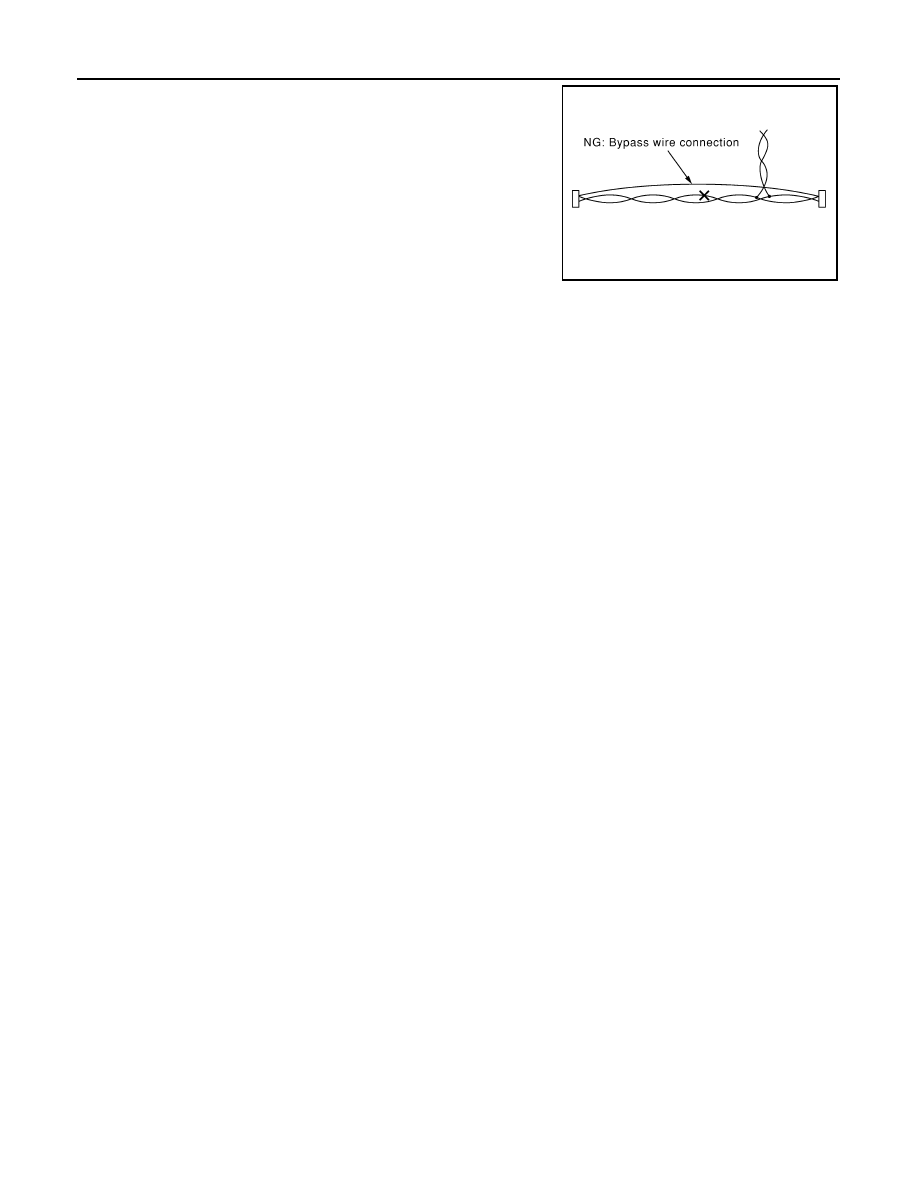
PRECAUTIONS
• Do not perform bypass wire connections for the repair parts. (The
spliced wire will become separated and the characteristics of
twisted line will be lost.)
PKIA0307E
AV
PREPARATION
AV-159
< PREPARATION >
[NAVIGATION (SINGLE MONITOR)]
C
D
E
F
G
H
I
J
K
L
M
B
A
O
P
PREPARATION
PREPARATION
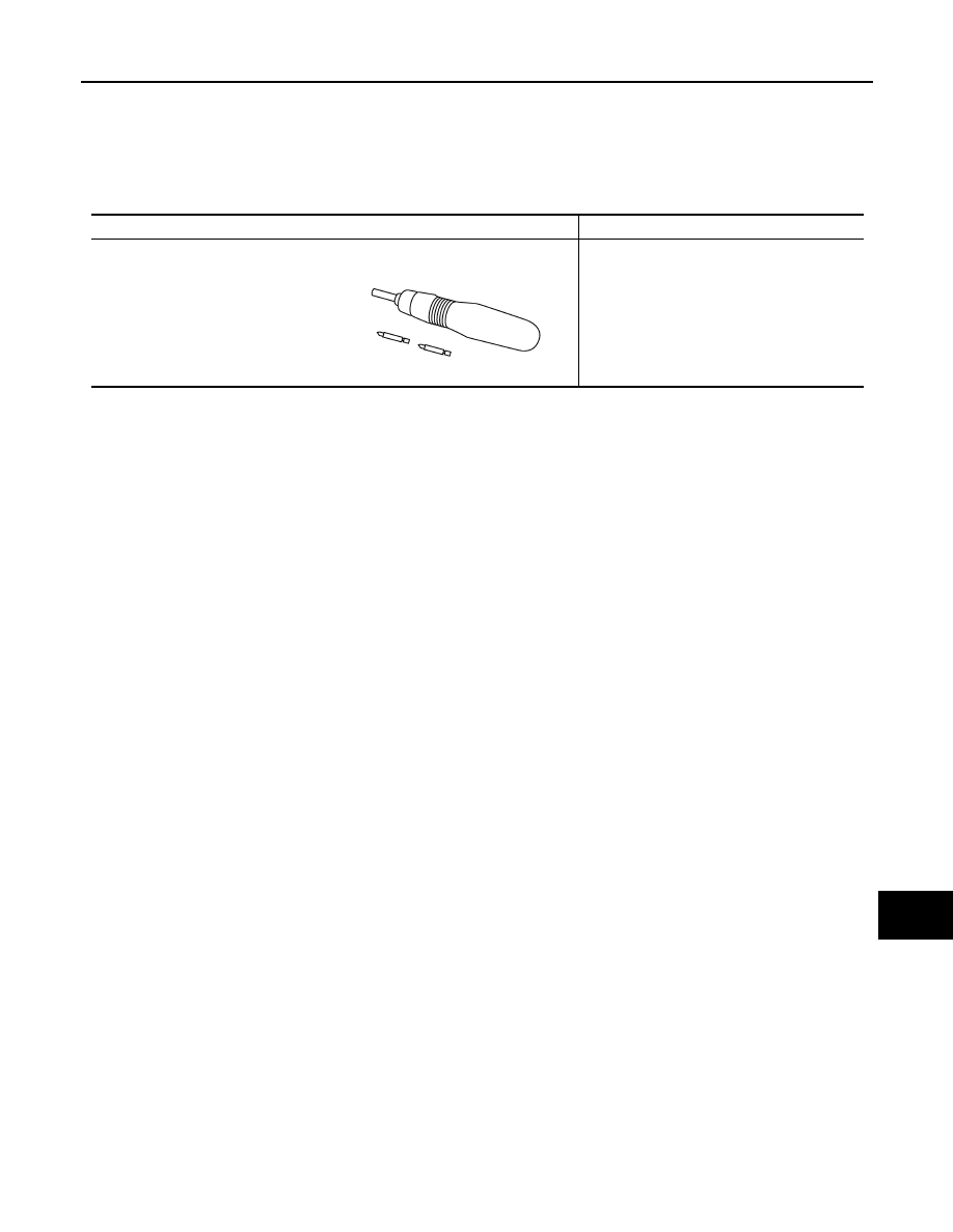
Commercial Service Tools
INFOID:0000000005475452
Tool name
Description
Power tool
Loosening screws
PBIC0191E
AV-160
< SYSTEM DESCRIPTION >
[NAVIGATION (SINGLE MONITOR)]
COMPONENT PARTS
SYSTEM DESCRIPTION
COMPONENT PARTS
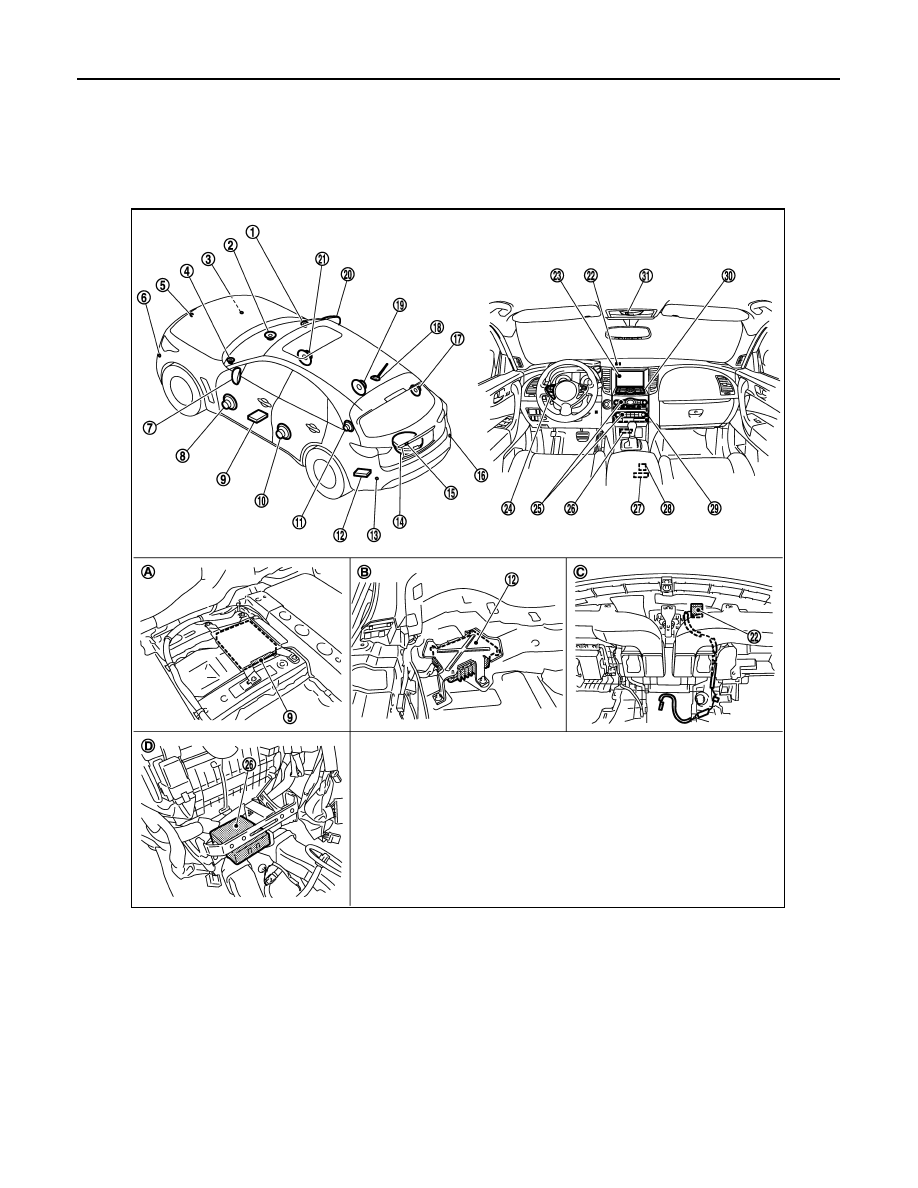
Component Parts Location
INFOID:0000000005475010
1.
Front squawker RH
2.
Center speaker
3.
Corner sensor front RH
4.
Front squawker LH
5.
Front camera
6.
Corner sensor front LH
7.
Side camera LH
8.
Front door speaker LH
9.
Around view monitor control unit
10. Rear door speaker LH
11. Rear squawker LH
12. BOSE amp.
13. Corner sensor rear LH
14. Woofer
15. Rear camera
16. Corner sensor rear RH
17. Rear squawker RH
18.
Antenna base (antenna amp. and
satellite antenna)
19. Rear door speaker RH
20.
Side camera RH and infrared LED
(auxiliary lighting)
21. Front door speaker RH
22. GPS antenna
23. Front display unit
24. Steering switch
JSNIA2264ZZ
Нет комментариевНе стесняйтесь поделиться с нами вашим ценным мнением.
Текст