Infiniti FX35, FX50 (S51). Manual — part 95
AV
REAR VIEW CAMERA
AV-153
< REMOVAL AND INSTALLATION >
[WITHOUT NAVIGATION]
C
D
E
F
G
H
I
J
K
L
M
B
A
O
P
REAR VIEW CAMERA
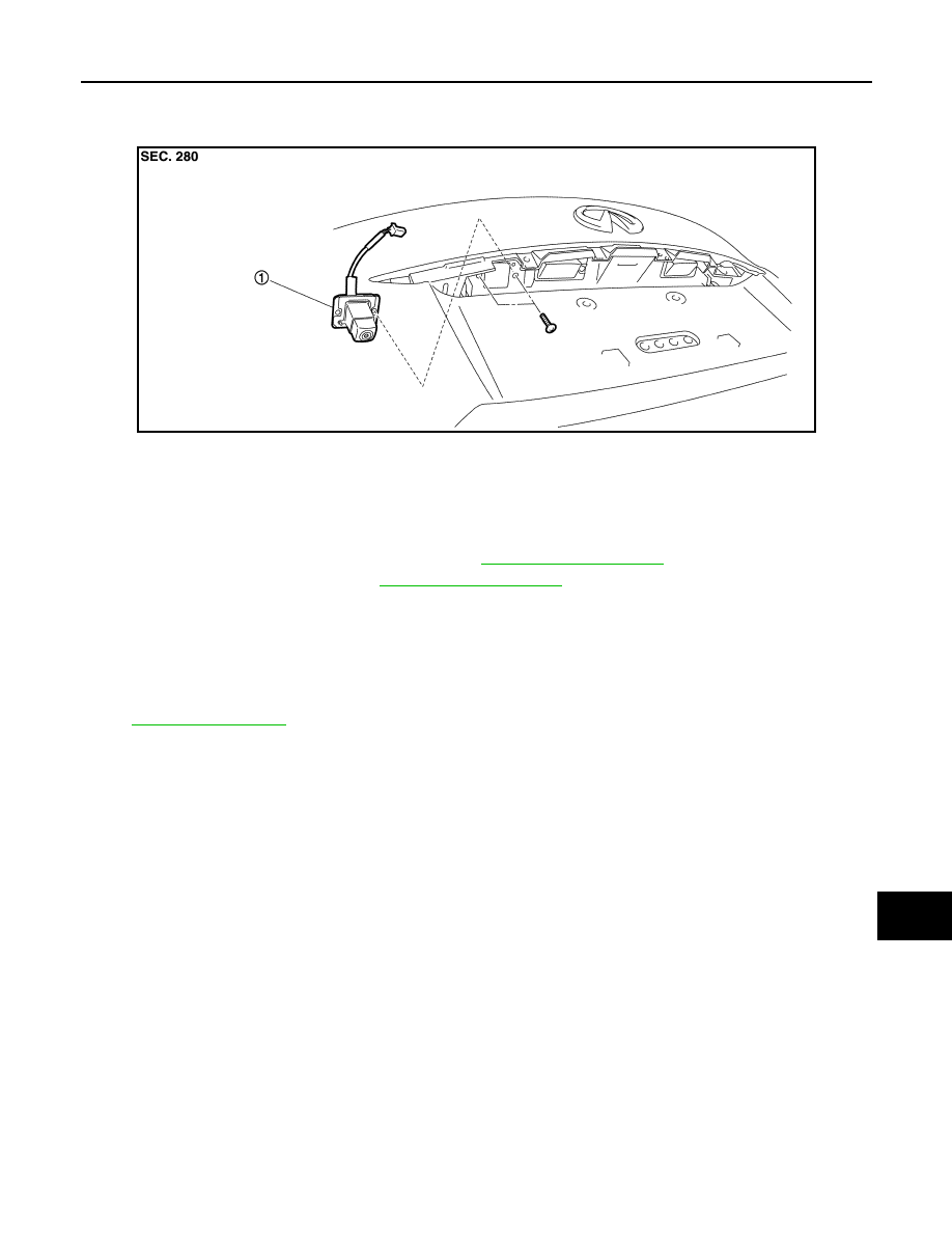
Exploded View
INFOID:0000000005246912
Removal and Installation
INFOID:0000000005246913
REMOVAL
1.
Remove back door outside finisher upper. Refer to
2.
Remove door handle cover. Refer to
.
3.
Remove rear view camera mounting screws and rear view camera harness connector.
4.
Remove rear view camera.
INSTALLATION
1.
Installation is the reverse order of removal.
2.
Adjust the guide line position if the guide line position is shifted after installing the rear view camera. Refer
to
.
JSNIA1470ZZ
1.
Rear view camera
AV-154
< REMOVAL AND INSTALLATION >
[WITHOUT NAVIGATION]
REAR VIEW CAMERA
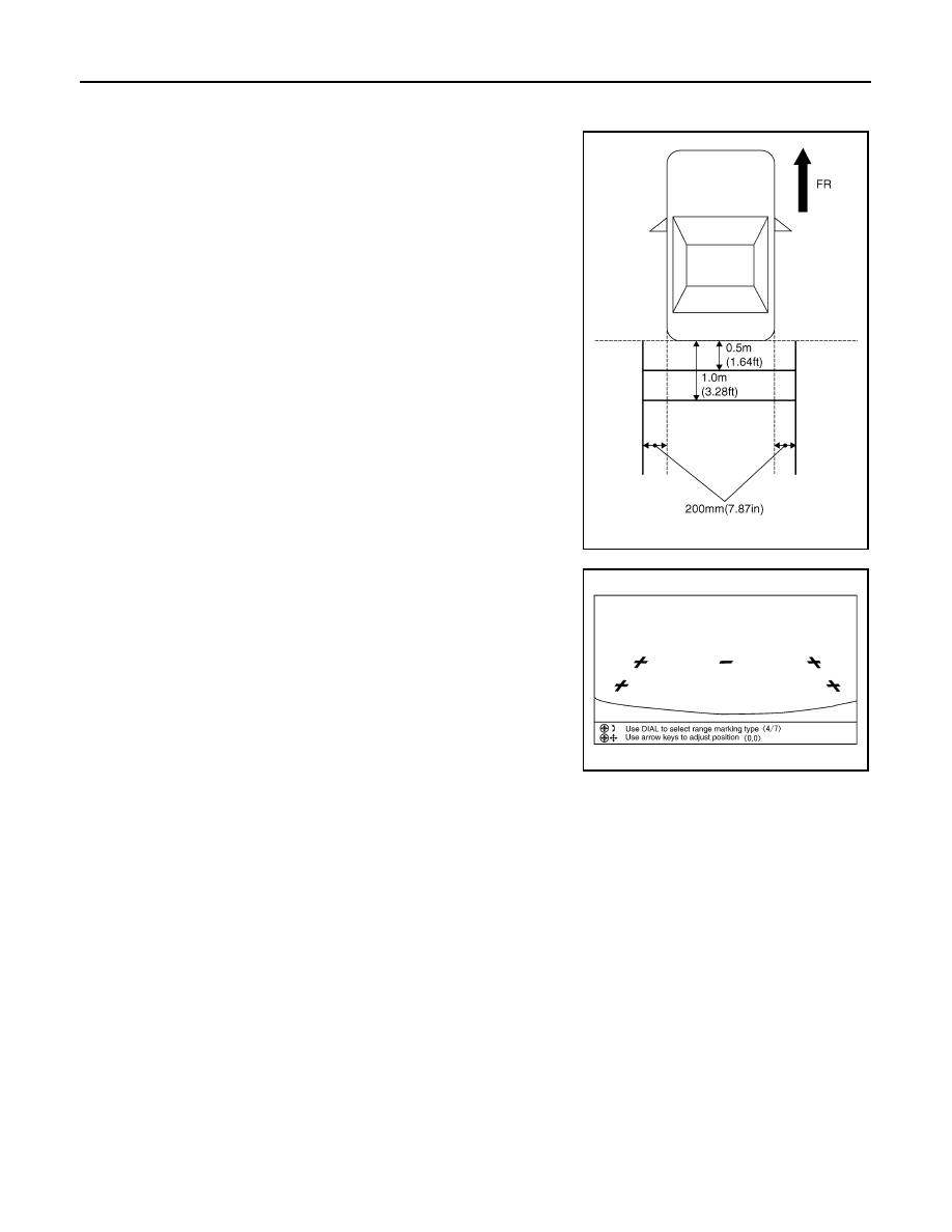
Adjustment
INFOID:0000000005246914
1.
Draw lines on rearward area of the vehicle passing through the
following points: 200 mm (7.87 in) from both sides of the vehicle,
and 0.5 m (1.64 ft), 1.0 m (3.28 ft) from the rear end of the
bumper.
2.
Set into “Adjust offset of rear view camera” mode of Confirma-
tion/Adjustment mode.
3.
Rotate the center dial, and then select the guiding line pattern so
that its angle is aligned with the correction line of the rear of the
vehicle.
4.
Fine adjust the guiding line so that its position is aligned to the
correction line by pressing the up/down/left/right switches.
Pressing “ENTER” enable the camera control unit to memory
the adjusted guiding line position.
CAUTION:
Never operate other function such as pressing BACK while writing index data.
If Confirmation/Adjustment mode does not function in the above procedure, perform one of the
following service to adjust the index again.
• Remove battery for five min. Then reconnect battery.
• Remove camera control unit connector for five min. Then reconnect camera control unit connec-
tor.
SKIB3691E
Selected pattern
: 7
Up/Down adjustment range
:
−
20 – 20
Left/Right adjustment range
:
−
20 – 20
SKIB3689E
AV
TEL ADAPTER UNIT
AV-155
< REMOVAL AND INSTALLATION >
[WITHOUT NAVIGATION]
C
D
E
F
G
H
I
J
K
L
M
B
A
O
P
TEL ADAPTER UNIT
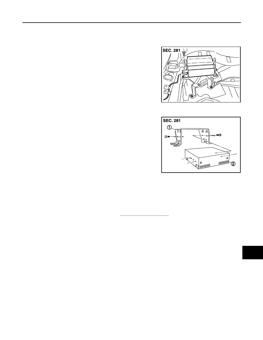
Exploded View
INFOID:0000000005530329
REMOVAL
DISASSEMBLY
Removal and Installation
INFOID:0000000005530330
REMOVAL
1.
Remove luggage floor spacer (LH). Refer to
.
2.
Remove TEL adapter unit screws, disconnect TEL adapter unit connector and remove the TEL adapter
unit.
INSTALLATION
Install in the reverse order of removal.
JSNIA2268ZZ
1.
TEL adapter unit
JSNIA2269ZZ
1.
Bracket
2.
TEL adapter unit
AV-156
< REMOVAL AND INSTALLATION >
[WITHOUT NAVIGATION]
ANTENNA FEEDER
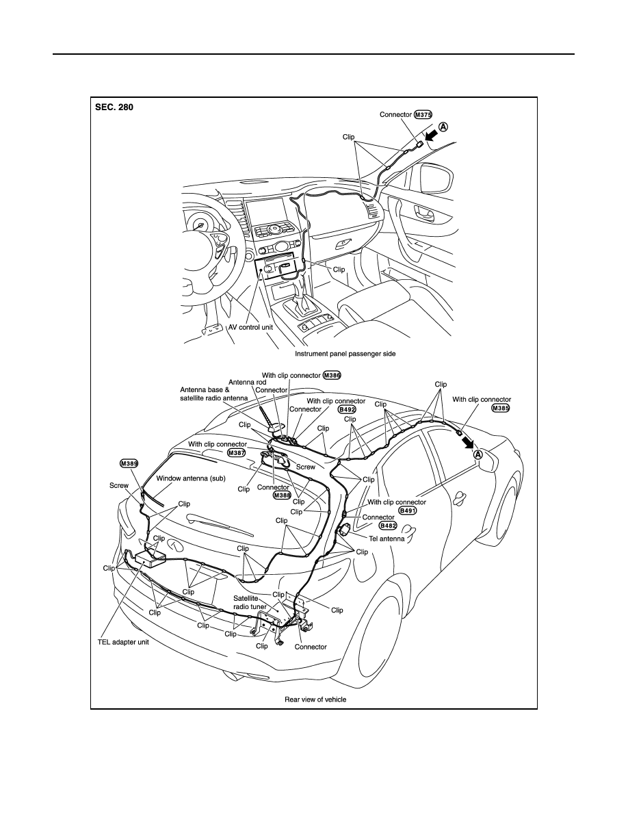
ANTENNA FEEDER
Feeder Layout
INFOID:0000000005246919
JSNIA2459GB
Нет комментариевНе стесняйтесь поделиться с нами вашим ценным мнением.
Текст