Infiniti FX35, FX50 (S51). Manual — part 1209
INL-36
< DTC/CIRCUIT DIAGNOSIS >
HOSPITALITY LIGHTING POWER SUPPLY CIRCUIT 3
HOSPITALITY LIGHTING POWER SUPPLY CIRCUIT 3
Description
INFOID:0000000005245569
Total illumination control unit provides the following illuminations power supply according to the battery saver
signal from BCM.
Illuminations
• Trip computer switch
• Illumination control switch
• Multifunction switch
• Climate controlled seat switch
• LDW switch
• Snow mode switch
• Door mirror remote control switch
• AFS OFF switch
• Headlamp aiming switch
• Mode select switch
• Clock
• Steering switch
• IBA OFF switch
• DCA switch
• VDC OFF switch
Diagnosis Procedure
INFOID:0000000005245570
CAUTION:
Check the following circuit first if the other room lamps (Map lamp, personal lamps, foot lamps, puddle
lamps, etc.) are not turned ON.
• Power supply and ground circuit of total illumination control unit: Refer to
NATION CONTROL UNIT : Diagnosis Procedure"
.
• Battery saver signal circuit: Refer to
1.
CHECK HOSPITALITY LIGHTING POWER SUPPLY 3 OUTPUT
CONSULT-III ACTIVE TEST
1.
Turn ignition switch ON.
2.
Set the illumination control switch in maximum.
3.
Select “BATTERY SAVER” of BCM (BATTERY SAVER) active test item.
4.
While operating the test item, check voltage between total illumination control unit harness connector and
ground.
Is the measurement value normal?
YES
>> GO TO 2.
NO
>> GO TO 3.
2.
CHECK HOSPITALITY LIGHTING POWER SUPPLY 3 CIRCUIT FOR OPEN
1.
Turn ignition switch OFF.
2.
Disconnect the total illumination control unit connector and each illumination connectors.
3.
Check continuity between total illumination control unit harness connector and each illumination harness
connectors.
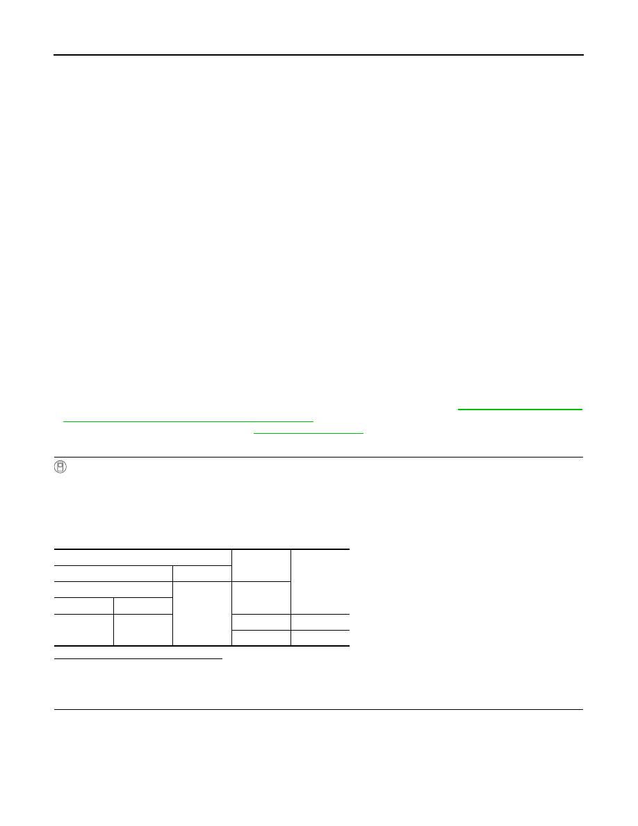
Terminals
Test item
Voltage
(Approx.)
(+)
(
−
)
Total illumination control unit
Ground
BATTERY
SAVER
Connector
Terminal
M129
33
Off
0 V
On
12 V
HOSPITALITY LIGHTING POWER SUPPLY CIRCUIT 3
INL-37
< DTC/CIRCUIT DIAGNOSIS >
C
D
E
F
G
H
I
J
K
M
A
B
INL
N
O
P
Does continuity exist?
YES
>> Hospitality lighting power supply 3 circuit is normal.
NO
>> Repair the harnesses or connectors.
3.
CHECK HOSPITALITY LIGHTING POWER SUPPLY 3 CIRCUIT FOR SHORT
Check continuity between total illumination control unit harness connector and ground.
Does continuity exist?
YES
>> Repair the harnesses or connectors.
NO
>> Replace the total illumination control unit.
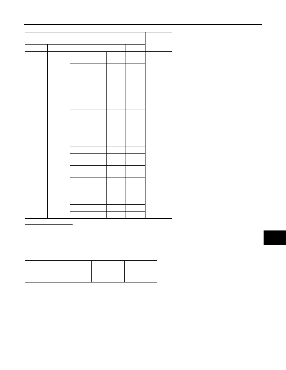
Total illumination con-
trol unit
Illuminations
Continuity
Connector
Terminal
Connector
Terminal
M129
33
Meter control
switch
M54
4
Existed
Multifunction
switch
M72
4
Climate controlled
seat switch
(driver side)
M177
7
Climate controlled
seat switch
(passenger side)
M178
7
LDW switch
M29
5
Snow mode
switch
M176
5
Door mirror
remote control
switch
M20
16
AFS OFF switch
M21
5
Headlamp aiming
switch
M15
3
Mode select
switch
M179
4
Clock
M74
2
Combination
switch
M36
23
IBA OFF switch
M184
5
DCA switch
M18
3
VDC OFF switch
M19
3
Total illumination control unit
Ground
Continuity
Connector
Terminal
M129
33
Not existed
INL-38
< DTC/CIRCUIT DIAGNOSIS >
MAP LAMP CIRCUIT
MAP LAMP CIRCUIT
Description
INFOID:0000000005245571
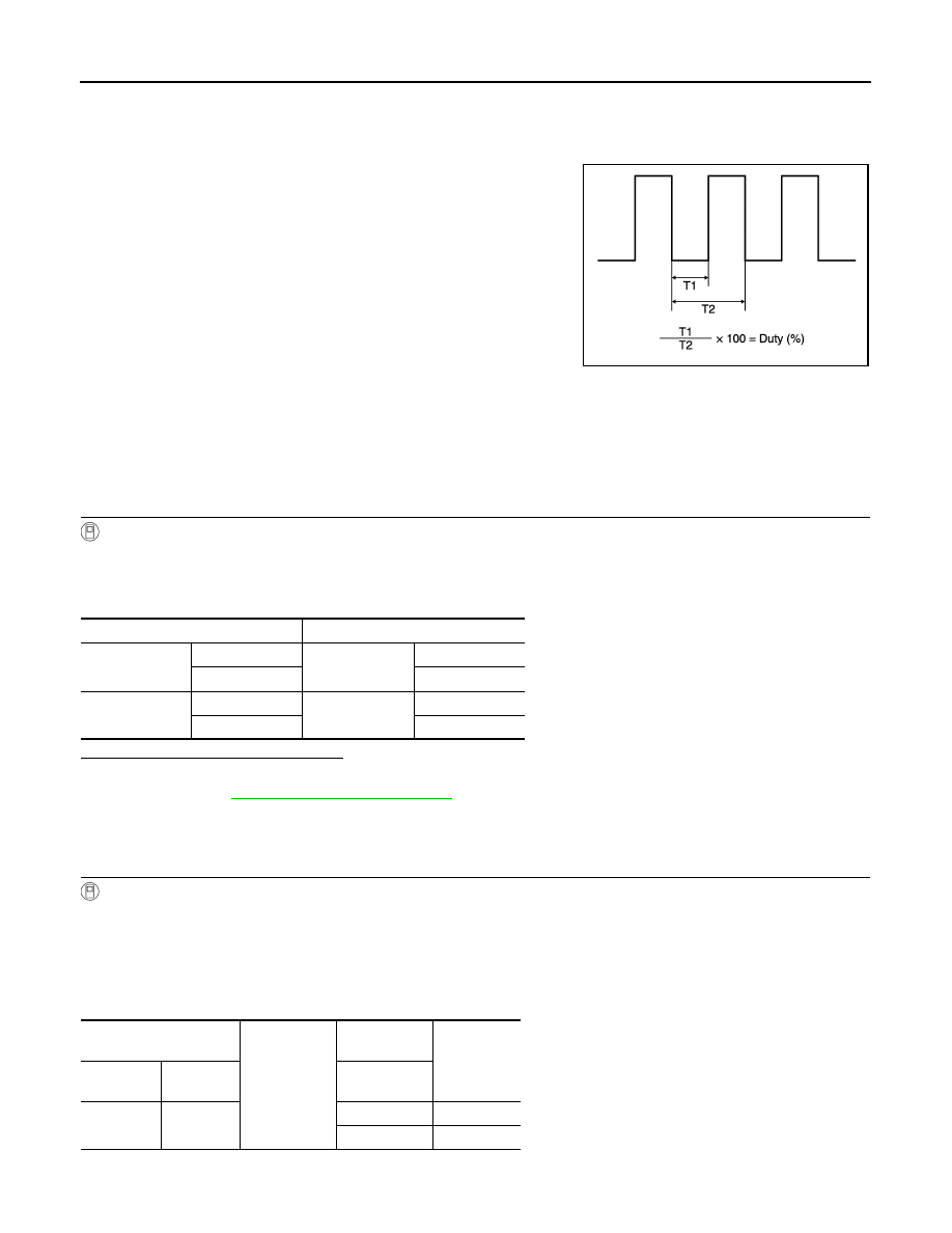
Controls the lamp (ground side) by PWM signal (duty) when the map
lamp main switch is DOOR.
Component Function Check
INFOID:0000000005245572
CAUTION:
Check the following item first.
• Hospitality lighting power supply 1 circuit (When both side lamps are not turned ON.)
• Map lamp bulbs
1.
CHECK MAP LAMP CONTROL FUNCTION
CONSULT-III ACTIVE TEST
1.
Turn ignition switch ON.
2.
Select “MAP LAMP-DR” or “MAP LAMP-AS” of TOTAL ILLUM C/U active test item.
3.
While operating the test items, check map lamps operation.
Are the map lamps turned ON/OFF?
YES
>> Map lamp circuit is normal.
NO
>> Refer to
.
Diagnosis Procedure
INFOID:0000000005245573
1.
CHECK MAP LAMP CONTROL OUTPUT
CONSULT-III ACTIVE TEST
1.
Turn ignition switch ON.
2.
Switch map lamp main switch DOOR.
3.
Select “MAP LAMP-DR” or “MAP LAMP-AS” of TOTAL ILLUM C/U active test item.
4.
While operating the test items, check voltage between total illumination control unit harness connector
and ground.
Driver side
JPLIA1210GB
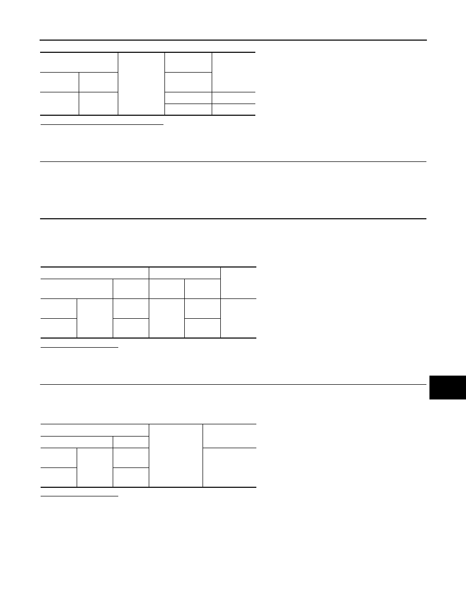
Test item
Operation
MAP LAMP-DR
On
Map lamp
(driver side)
ON
Off
OFF
MAP LAMP-AS
On
Map lamp
(passenger side)
ON
Off
OFF
Total illumination control
unit
Ground
Test item
Voltage
(Approx.)
Connector
Terminal
MAP LAMP-
DR
M129
18
On
0 V
Off
12 V
MAP LAMP CIRCUIT
INL-39
< DTC/CIRCUIT DIAGNOSIS >
C
D
E
F
G
H
I
J
K
M
A
B
INL
N
O
P
Passenger side
Is the measurement value normal?
Fixed at 12 V>>Replace the total illumination control unit.
Fixed at 0 V>>GO TO 2.
2.
CHECK THE SYMPTOM
Check that the lamp fixed to ON or OFF.
Fixed OFF>>GO TO 3.
Fixed ON>>GO TO 4.
3.
CHECK MAP LAMP CONTROL CIRCUIT FOR OPEN
1.
Turn ignition switch OFF.
2.
Disconnect the total illumination control unit and map lamp connector.
3.
Check continuity between the total illumination control unit harness connector and map lamp harness con-
nector.
Does continuity exist?
YES
>> Replace the map lamp assembly.
NO
>> Repair the harnesses or connectors.
4.
CHECK MAP LAMP CONTROL CIRCUIT FOR SHORT
1.
Turn ignition switch OFF.
2.
Disconnect the total illumination control unit and map lamp connector.
3.
Check continuity between the total illumination control unit harness connector and ground.
Does continuity exist?
YES
>> Repair the harnesses or connectors.
NO
>> Replace the total illumination control unit.
Total illumination control
unit
Ground
Test item
Voltage
(Approx.)
Connector
Terminal
MAP LAMP-
AS
M129
12
On
0 V
Off
12 V
Total illumination control unit
Map lamp
Continuity
Connector
Terminal
Connec-
tor
Terminal
Driver
side
M129
18
R15
7
Existed
Passen-
ger side
12
9
Total illumination control unit
Ground
Continuity
Connector
Terminal
Driver
side
M129
18
Not existed
Passen-
ger side
12
Нет комментариевНе стесняйтесь поделиться с нами вашим ценным мнением.
Текст