Infiniti FX35, FX50 (S51). Manual — part 151
AV
SYSTEM
AV-377
< SYSTEM DESCRIPTION >
[NAVIGATION (TWIN MONITOR)]
C
D
E
F
G
H
I
J
K
L
M
B
A
O
P
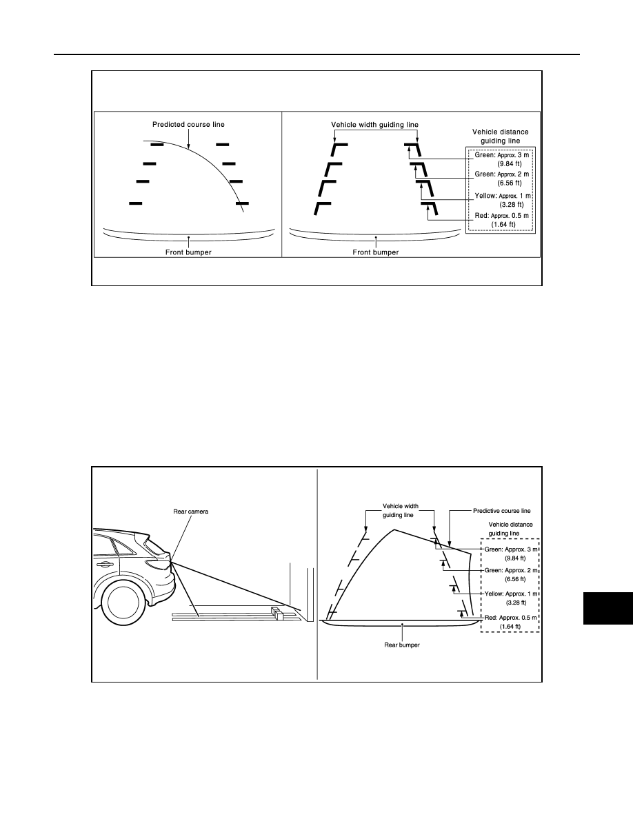
Front view guiding lines
REAR VIEW
• The rear view image is from the rear camera.
• When the selector lever is in the reverse position, the rear view is displayed. Backing and parking are
improved by the images from Birds-Eye view and Front-Side view. The rear wide view function allows the
display of an image with a 180
°
horizontal angle.
• Display the vehicle width guiding line and vehicle distance guiding line in Rear view and display the predic-
tive course line according to the steering angle (except when using the rear wide view function).
• The predictive course line is not displayed at the steering neutral position.
• AV control unit is connected to the steering angle sensor and receives the steering angle signal via CAN
communication. AV control unit is transmits steering angle signal to around view monitor control unit via AV
communication.
• Around view monitor control unit controls the direction and distance of predictive course line according to the
sensor signal from steering angle sensor.
Rear view guiding lines
FRONT-SIDE VIEW
• The front-side view image is from the side camera RH.
• In Front-Side view, display the vehicle distance guiding line and vehicle width guiding line.
• The infrared LED illumination is installed on the door mirror RH to illuminate around the front wheels.
JSNIA0770GB
JSNIA2407GB

AV-378
< SYSTEM DESCRIPTION >
[NAVIGATION (TWIN MONITOR)]
SYSTEM
Front-side view area and guiding line
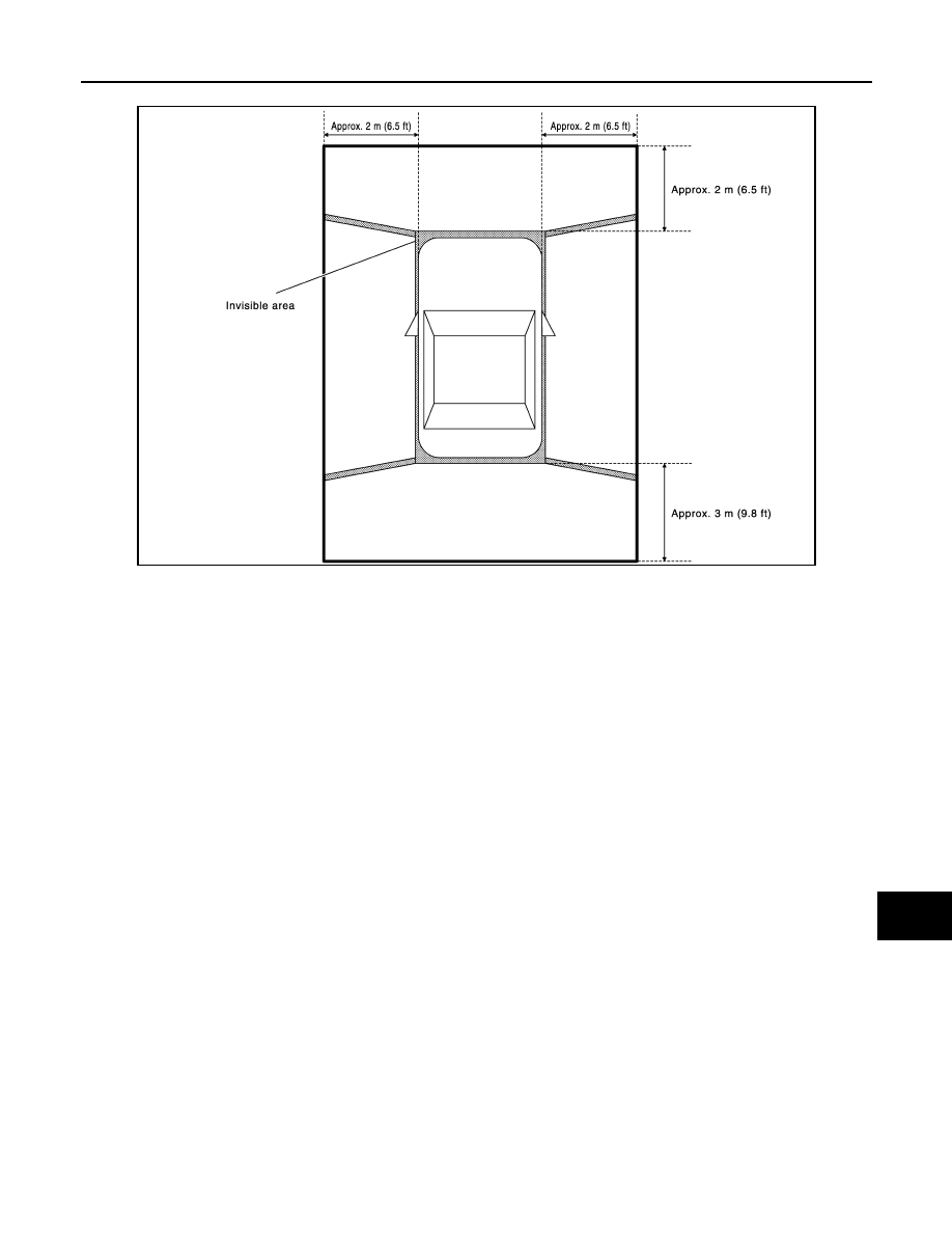
BIRDS-EYE VIEW
• The image from the 4 cameras is cut out and converted into the overhead view, and the surroundings of the
vehicle is displayed in birds-eye view.
• In Birds-Eye view, the invisible area is displayed on the image to specify the boundary of the 4 cameras.
• The invisible area is displayed in yellow in the Birds-Eye view after turning the ignition switch ON as an infor-
mation for the user. (OFF setting can be performed)
Birds-Eye view display image
JSNIA0771GB
JSNIA1441GB
AV
SYSTEM
AV-379
< SYSTEM DESCRIPTION >
[NAVIGATION (TWIN MONITOR)]
C
D
E
F
G
H
I
J
K
L
M
B
A
O
P
Birds-Eye view display area
Camera Image Operation Principle
• If the information writing to around view monitor control unit and the information from the camera are not
matched, the applicable camera position is indicated as an error on the Birds-Eye view display. (Calibration
operation is necessary when replacing each camera or when replacing around view monitor control unit.)
• Around view monitor control unit receives the camera switch signal from AV control unit via AV communica-
tion by pressing the “CAMERA” switch of multifunction switch.
• Around view monitor control unit that receives the camera switch signal supplies the power to each camera
and inputs the camera image from each camera.
• When the selector lever is in the reverse position, around view monitor control unit receives the reverse sig-
nal, supplies the power to each camera, and inputs the camera image from each camera.
• Around view monitor control unit that receives the camera image signal from each camera cuts out the
required screen for each view, superimposes the camera image, vehicle icon, guiding lines, sonar indicator,
and outputs them to the front display unit.
CAMERA ASSISTANCE SONAR FUNCTION
• Install the corner sensor on the front bumper and rear bumper. It detects the obstacles around the vehicle
when the around view monitor is displayed. It warns of the approach to the obstacles with the buzzer and
indicator in the display linked with the around view monitor system.
• It displays the distance between the bumper and obstacle with the color of sonar indicator in the display and
the blinking cycle of indicator in 3 stages.
• The buzzer warns of the distance to the obstacles with the cycle in 3 stages.
System Operation Description
• Around view monitor control unit transmits the sonar operation signal via AV communication to sonar control
unit to control the operation of sonar indicator and sonar buzzer.
• Sonar control unit that receives the sonar operation signal from around view monitor control unit transmits
the detection signal and detection distance signal according to the signal from corner sensor via AV commu-
nication to around view monitor control unit. Around view monitor control unit operates the applicable sonar
indicator.
• When receiving a sonar operation signal from the around view monitor control unit, the sonar control unit
converts a signal transmitted from the corner sensor into a detection distance signal and transmits it to the
AV control unit via AV communication. When receiving the detection signal, the AV control unit activates
each speaker via BOSE amp.
JSNIA0775GB
AV-380
< SYSTEM DESCRIPTION >
[NAVIGATION (TWIN MONITOR)]
SYSTEM
• Sonar control unit has the diagnosis function. It can detect the corner sensor malfunction or sensor harness
open circuit. It transmits the diagnosis results to around view monitor control unit and always displays the
sonar indicator in red to inform the user.
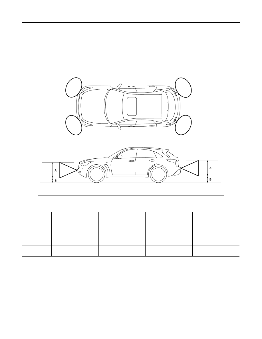
Obstacle Detection Distance
• Sonar control unit changes the outputs of the sonar indicator and warning buzzer in 3 stages according to
the obstacle detection distance from the corner sensor.
• The sonar control unit can change the setting of obstacle detection distance in 4 stages.
Obstacle detection image
Detection distance
Sonar Indicator Display
• Around view monitor control unit that receives the detection signal and detection distance signal from sonar
control unit displays the sonar indicator on display.
• Around view monitor control unit changes the color or blinking cycle of the indicator according to the detec-
tion distance.
JSNIA1430ZZ
A.
Approx. 50 cm (19.6 in)
B.
Approx. 15 cm (5.9 in)
Warning item
Sensitivity level 1
(Faster warning)
Sensitivity level 2
(Default value)
Sensitivity level 3
(Slower warning)
Sensitivity level 4
(Slowest warning)
First stage
warning
70 – 80 cm (27.5 – 31.4 in)
60 – 70 cm (23.6 – 27.5 in)
50 – 60 cm (19.6 – 23.6 in)
40 – 50 cm (15.7 – 19.6 in)
Second stage
warning
50 – 70 cm (19.6 – 27.5 in)
40 – 60 cm (15.7 – 23.6 in)
30 – 50 cm (11.8 – 19.6 in)
30 – 40 cm (11.8 – 15.7 in)
Third stage
warning
Less than 50 cm (19.6 in)
Less than 40 cm (15.7 in)
Less than 30 cm (11.8 in)
Less than 30 cm (11.8 in)
Нет комментариевНе стесняйтесь поделиться с нами вашим ценным мнением.
Текст