Infiniti FX35, FX50 (S51). Manual — part 149
AV
SYSTEM
AV-369
< SYSTEM DESCRIPTION >
[NAVIGATION (TWIN MONITOR)]
C
D
E
F
G
H
I
J
K
L
M
B
A
O
P
SYSTEM
MULTI AV SYSTEM
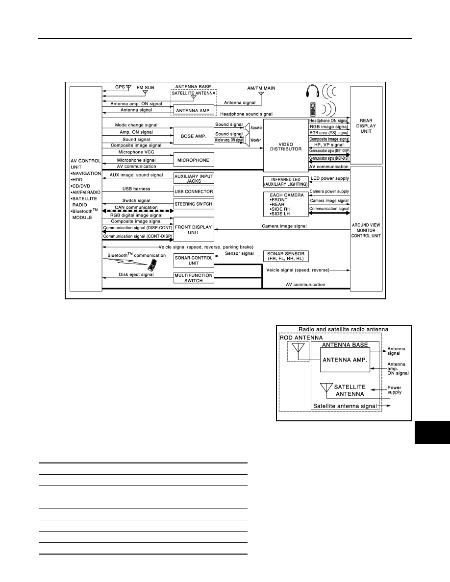
MULTI AV SYSTEM : System Diagram
INFOID:0000000005503167
NOTE:
• The name MULTIFUNCTION SWITCH indicates the integration of PRESET SWITCH and MULTIFUNCTION
SWITCH virtually.
• An antenna base integrated with antenna amp. is adopted.
MULTI AV SYSTEM : System Description
INFOID:0000000005503168
Multi AV system means that the following systems are integrated.
JSNIA2455GB
JSNIA1603GB
FUNCTION NAME
Navigation system function
Audio function
DVD play function
Hands-free phone function
Mobile entertainment system
Auxiliary input function
USB connection function
AV-370
< SYSTEM DESCRIPTION >
[NAVIGATION (TWIN MONITOR)]
SYSTEM
COMMUNICATION SIGNAL
• AV control unit function by transmitting/receiving data one by one with each unit (slave unit) that configures
them completely as a master unit by connecting between units that configure MULTI AV system with two AV
communication lines (H, L).
• Two AV communication lines (H, L) adopt a twisted pair line that is resistant to noise.
• AV control unit is connected by CAN communication, and it receives data signal from ECM, unified meter
and A/C amp. It computes and displays fuel economy information value with the obtained information.
• AV control unit is connected with display and serial communication, and it transmits the required signal of
display and display control and receives the response signal from display.
NAVIGATION SYSTEM FUNCTION
Description
• The AV control unit controls navigation function while GPS tuner has built-in map data, GYRO (angle speed
sensor), on the HDD (Hard Disk Drive).
• The AV control unit inputs operation signal with communication signal, through display (touch panel) and
multifunction switch and steering switch.
• Guide sound is output to front speaker through BOSE amp. from AV control unit when operating navigation
system.
• A vehicle position is calculated with the GYRO (angle speed sensor), vehicle sensor, signal from GPS satel-
lite and map data stored on HDD (Hard Disk Drive), and transmits the map image signal (RGB image, RGB
area, RGB image synchronizing) to the display.
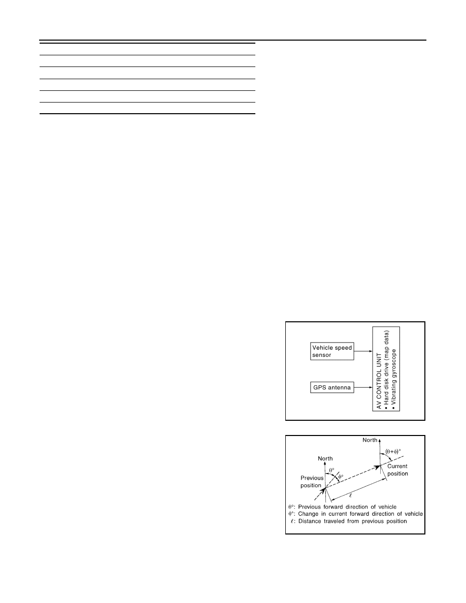
Position Detection Principle
The navigation system periodically calculates the current vehicle
position according to the following three types of signals.
• Travel distance of the vehicle as determined by the vehicle speed
sensor
• Vehicle turning angle determined by the gyroscope (angular speed
sensor)
• The travel direction of the vehicle determined by the GPS antenna
(GPS information)
The current position of the vehicle is then identified by comparing the
calculated vehicle position with map data, which is stored in the HDD
(Hard Disk Drive) (map-matching), and indicated on the screen with
a current location mark. More accurate data is used by comparing
position detection results from GPS to the map-matching.
The current position is calculated by detecting the travel distance
from the previous calculation point, and its direction change.
• Travel distance
The travel distance is generated from the vehicle speed sensor
input signal. The automatic distance correction function is adopted
for preventing a miss-detection of the travel distance because of
tire wear etc.
• Travel direction
The gyroscope (angular velocity sensor) and GPS antenna (GPS
information) generate the change of the travel direction. Both have
advantages and disadvantages as per the following descriptions.
Voice recognition function
Touch panel function
Around view monitor function
Camera assistance sonar system
Vehicle information function
FUNCTION NAME
JSNIA0177GB
SEL684V
AV
SYSTEM
AV-371
< SYSTEM DESCRIPTION >
[NAVIGATION (TWIN MONITOR)]
C
D
E
F
G
H
I
J
K
L
M
B
A
O
P
Input signals are prioritized in each situation. However, this order of priority may change in accordance with
more detailed travel conditions so that the travel direction is detected more accurately.
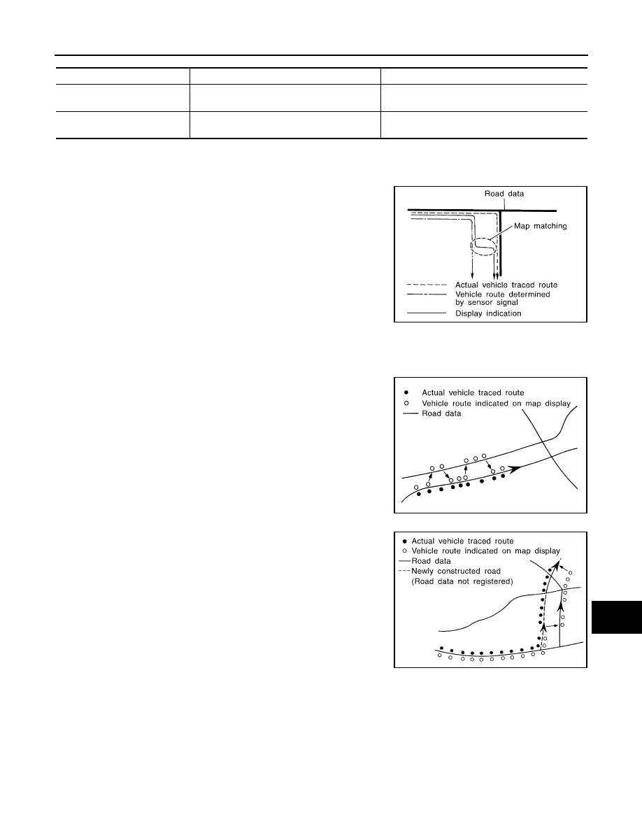
Map-matching
Map-matching repositions the vehicle on the road map when a new
location is judged to be more accurate. This is done by comparing
the current vehicle position (calculated by the normal position detec-
tion method) from the map data stored in the HDD (Hard Disk Drive).
There is a possibility that the vehicle position may not be corrected in the following case, and when vehicle is
driven over a certain distance or time in which GPS information is hard to receive. Correct manually the cur-
rent location mark on the screen.
• In map-matching, several alternative routes are prepared and pri-
oritized in addition to the road judged as currently driving on.
Therefore, due to errors in the distance and/or direction, an incor-
rect road may be prioritized, and the current location mark may be
repositioned to the incorrect road.
If two roads are running in parallel, they are of the same priority.
Therefore, the current location mark may appear on either of them
alternately, depending on maneuvering of the steering wheel and
configuration of the road, etc.
• Map-matching does not function correctly when road on which the
vehicle is driving is new, etc. and not recorded in the map data.
Also, map-matching does not function correctly when road pattern
stored in the map data and the actual road pattern are different due
to repair, etc.
Therefore, the map-matching function judges other road as a cur-
rently driving road if the road is not in the map, and displays the
current location mark on it. Later, the current location mark may be
repositioned to the road if the correct road is detected.
• Effective range for comparing the vehicle position and travel direc-
tion calculated by the distance and direction with the road data is
limited. Therefore, correction by map-matching is not possible
when there is an excessive gap between current vehicle position and the position on the map.
GPS (Global Positioning System)
Type
Advantage
Disadvantage
Gyroscope (angular velocity
sensor)
The turning angle is precisely detected.
Errors are accumulated when driving a long dis-
tance without stopping.
GPS antenna (GPS informa-
tion)
The travel direction (North/South/East/West) is
detected.
The travel direction is not precisely detected when
driving slowly.
SEL685V
SEL686V
JSNIA0180GB
AV-372
< SYSTEM DESCRIPTION >
[NAVIGATION (TWIN MONITOR)]
SYSTEM
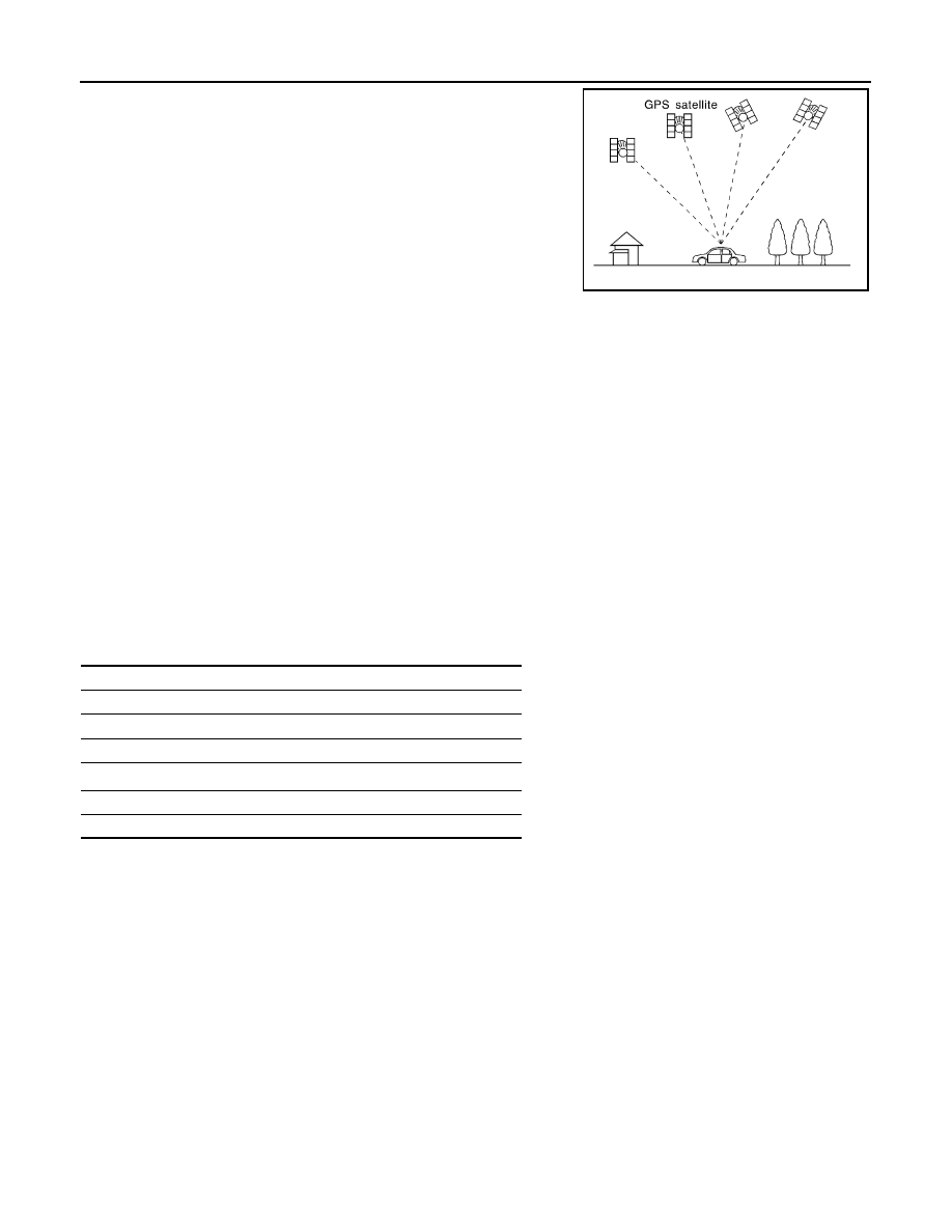
GPS (Global Positioning System) is developed for and is controlled
by the US Department of Defense. The system utilizes GPS satel-
lites (NAVSTAR), transmitting out radio waves while flying on an orbit
around the earth at an altitude of approximately 21,000 km (13,049
mile).
The receiver calculates the travel position in three dimensions (lati-
tude/longitude/altitude) according to the time lag of the radio waves
that four or more GPS satellites transmit (three-dimensional position-
ing). The GPS receiver calculates the travel position in two dimen-
sions (latitude/longitude) with the previous altitude data if the GPS
receiver receives only three radio waves (two-dimensional position-
ing). GPS position correction is not performed while stopping the
vehicle.
Accuracy of the GPS will deteriorate under the following conditions:
• In two-dimensional positioning, GPS accuracy will deteriorate when altitude of the vehicle position changes.
• The position of GPS satellite affects GPS detection precision. The position detection may not be precisely
performed.
• The position detection is not performed if GPS receiver does not receive radio waves from GPS satellites.
(Inside a tunnel, parking in a building, under an elevated highway etc.) GPS receiver may not receive radio
waves from GPS satellites if any object is placed on the GPS antenna.
NOTE:
• The detection result has an error of approximately 10 m (32.81 ft) even with a high-precision three dimen-
sional positioning.
• There may be cases when the accuracy is lowered and radio waves are stopped intentionally because the
GPS satellite signal is controlled by the US trace control center.
AUDIO FUNCTION
The audio system is equipped with the following functions. Each function is operated with multifunction switch,
preset switch, touch panel, steering switch or audio recognition. Operation status of audio is indicated at dis-
play.
Operating Signal
Audio system operation can be performed with multifunction switch, preset switch, steering switch, touch
panel function or voice recognition function.
• Operating signal is transmitted to AV control unit with AV communication when it is operated by multifunction
switch or preset switch. The disk ejection operating signal is performed by hardwire.
• Operating signal is transmitted to AV control unit with steering switch signal when it is operated by steering
switch.
Screen Display
Switching of display is performed with serial communication between front display unit and AV control unit.
AM/FM Radio Mode
• AM/FM radio tuner is built into AV control unit.
• Audio signal is received by rod antenna, next it is amplified by antenna amp., and finally it is input to AV con-
trol unit. Audio signal is input to BOSE amp., and BOSE amp. outputs to each speaker.
Satellite Radio Mode
• Satellite radio tuner is built into AV control unit.
SEL526V
FUNCTION
AM/FM radio
Satellite radio
CD
Bluetooth
™
audio
Music Box (Hard Disk Drive)
Driver's Audio Stage
Нет комментариевНе стесняйтесь поделиться с нами вашим ценным мнением.
Текст