Infiniti FX35, FX50 (S51). Manual — part 1202

INL-8
< SYSTEM DESCRIPTION >
INTERIOR ROOM LAMP CONTROL SYSTEM
Hospitality lighting functioning table
NOTE:
Li
g
h
t so
urce
Pus
h
-but
ton
i
gni
tio
n
sw
itch
il
lu
m
in
a
ti
on
Ma
p lam
p
an
d
Pers
on
al
la
mp
Pu
dd
le
la
mp
Mo
od
la
mp
s
(Door armrest)
Fo
ot l
a
mp
St
e
p
l
a
m
p
Ce
nt
er c
o
n
s
o
le
ind
ire
ct ill
um
in
ati
o
n
Ea
ch
il
lu
mi
nat
io
n
(Cl
o
c
k
, swi
tch
es
,
e
tc
.)
Me
ter ill
um
in
ati
o
n
A cl
os
e
d
oo
r
sid
e la
mp
An op
en
do
or
sid
e la
mp
Scene 1
• Door is unlocked
(Interior room
lamp timer func-
tion)
• Driver approach
to the vehicle
(Welcome light
function)
Heart
beat
(Pulse)
Dim
(30%)
ON
(100%)
OFF
OFF
OFF
OFF
OFF
OFF
Scene 2
Any door is opened
Dim
(30%)
1 sec.
delay
ON
(90%)
ON
(100%)
ON
(80%)
ON
Scene 3
All doors are
closed
Dim
(30%)
OFF
OFF
2.5 sec.
delay
ON
(100%)
Meter panel
illuminates
Scene 4
Ignition switch
ACC or ON
Steady
OFF
Dim
(10%)
ON
(10%)
OFF
Combina-
tion meter
activates
Scene 5
Engine start
Engine start
excitement
function
Scene 6
Engine running
OFF
Scene 7
Tail lamps ON
(Linked to illumina-
tion control switch)
Steady
Dim
(10%
MAX)
OFF
ON
(100%
MAX)
Dim
Scene 8
Map lamp main
switch ALL ON
—
ON
(100%)
—
—
—
—
ON
(100%)
—
—
Scene 6
Ignition switch OFF
Steady
Dim
(30%)
ON
(100%)
ON
(100%)
ON
(80%)
OFF
OFF
OFF
OFF
(Gradual
dimming)
Scene 7
Any door is opened
Dim
(30%)
1 sec.
delay
ON
(90%)
ON
OFF
Scene 8
All doors are
closed
Dim
(30%)
OFF
2.5 sec.
delay
ON
(100%)
Meter panel
illuminates
Scene 9
• Door is locked
• Battery saver ac-
tivates
OFF
OFF
OFF
OFF
OFF
OFF
OFF
OFF
INTERIOR ROOM LAMP CONTROL SYSTEM
INL-9
< SYSTEM DESCRIPTION >
C
D
E
F
G
H
I
J
K
M
A
B
INL
N
O
P
• Heart beat function of push-button ignition switch illumination can be set to OFF by CONSULT-III.
• Total illumination control unit controlled lamps fade-in/fade-out time can be set by CONSULT-III.
Refer to
INL-18, "CONSULT-III Function (TOTAL ILLUM C/U)"
.
TOTAL ILLUMINATION CONTROL UNIT
Total illumination control unit controls each lamp (ground side) by PWM signal (duty) depending on vehicle
conditions.
INTERIOR ROOM LAMP TIMER CONTROL
BCM operates the timer for a period of time when satisfying the timer operating condition. And it outputs the
room lamp timer signal to total illumination control unit while the timer counts the time.
Timer ON
• Door is unlocked.
• Welcome light function operating condition is satisfied.
Timer OFF
• Ignition switch is OFF
⇒
ON or ACC.
• Door is locked.
NOTE:
Interior room lamp timer can be set by CONSULT-III. Refer to
INL-22, "INT LAMP : CONSULT-III Function
.
STEP LAMP CONTROL
BCM controls the step lamp (ground-side) to turn the step lamp ON when any door switch is ON.
INL-10
< SYSTEM DESCRIPTION >
INTERIOR ROOM LAMP CONTROL SYSTEM
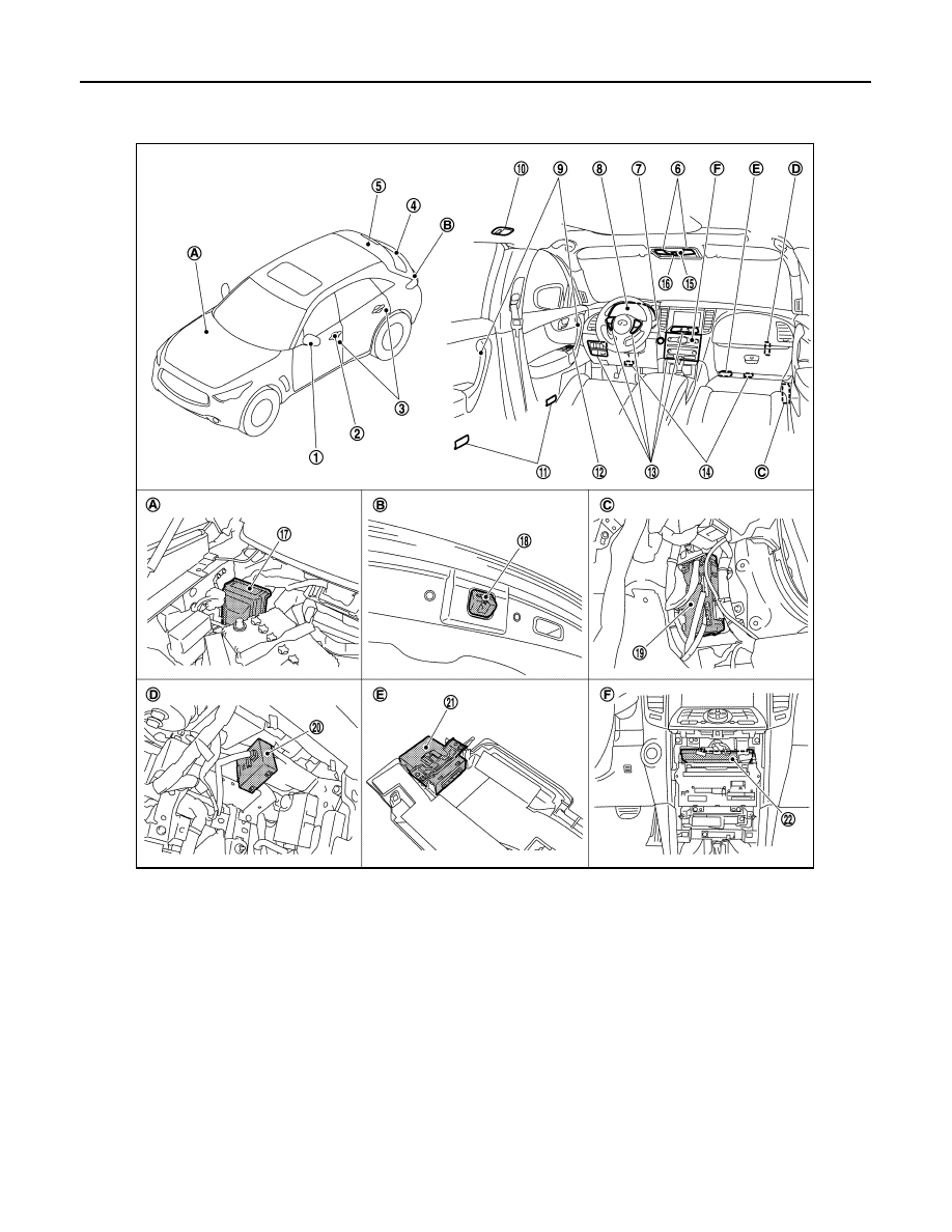
Component Parts Location
INFOID:0000000005245545
1.
Puddle lamp
2.
• Request switch
• Key cylinder lock/unlock
switch
3.
Door switch
4.
Luggage room lamp (Back door
side)
5.
Luggage room lamp (Lug-
gage side)
6.
Map lamp
7.
Push-button ignition switch illumi-
nation
8.
Combination meter
9.
Mood lamp
10. Personal lamp
11. Step lamp
12. Door lock/unlock switch
13. Illuminations
14. Foot lamp
15. Center console indirect illumination
16. Map lamp main switch
17. IPDM E/R
18. Back door switch
19. BCM
20. Remote keyless entry receiv-
er
21. Total illumination control unit
22. Unified meter and A/C amp.
A.
Engine room dash panel (RH)
B.
Back door lock assembly
C.
Dash side lower (passenger side)
D.
Over the glove box
E.
Instrument lower cover LH
F.
Behind the cluster lid C
JPLIA1248ZZ

INTERIOR ROOM LAMP CONTROL SYSTEM
INL-11
< SYSTEM DESCRIPTION >
C
D
E
F
G
H
I
J
K
M
A
B
INL
N
O
P
Component Description
INFOID:0000000005245546
Part
Description
Total illumination control unit
Controls each interior room lamp and each illumination depending on the vehicle con-
ditions and each signal.
BCM
• Outputs room lamp timer signal and battery saver signal to the total illumination con-
trol unit depending on the vehicle conditions.
• Turns the step lamp ON/OFF according to any door switch status.
• Controls welcome light function of Intelligent Key system.
Combination meter
• Illuminates the meter illumination according to request signals from BCM via CAN
communication (through the unified meter and A/C amp.).
• Outputs the illumination control signal to the total illumination control unit.
• Remote keyless entry receiver
• Outside key antenna
• Receives the lock/unlock signal from keyfob.
• Transmits the lock/unlock signal to BCM.
• Request switch
• Key cylinder lock/unlock switch
• Door lock/unlock switch
Inputs the lock/unlock signal to BCM.
Door switch
Inputs the door switch signal to BCM and the total illumination control unit.
Tail lamp relay
Inputs the tail lamp signal to the total illumination control unit.
Map lamp main switch
Inputs the map lamp switch signal to the total illumination control unit.
Нет комментариевНе стесняйтесь поделиться с нами вашим ценным мнением.
Текст