Infiniti FX35, FX50 (S51). Manual — part 82
AV
POWER SUPPLY AND GROUND CIRCUIT
AV-101
< DTC/CIRCUIT DIAGNOSIS >
[WITHOUT NAVIGATION]
C
D
E
F
G
H
I
J
K
L
M
B
A
O
P
POWER SUPPLY AND GROUND CIRCUIT
AV CONTROL UNIT
AV CONTROL UNIT : Diagnosis Procedure
INFOID:0000000005528981
1.
CHECK FUSE
Check for blown fuses.
Is the inspection result normal?
YES
>> GO TO 2.
NO
>> Be sure to eliminate cause of malfunction before installing new fuse.
2.
CHECK POWER SUPPLY CIRCUIT
Check voltage between AV control unit harness connectors and ground.
Is the inspection result normal?
YES
>> GO TO 3.
NO
>> Check harness between AV control unit and fuse.
3.
CHECK GROUND CIRCUIT
1.
Turn ignition switch OFF.
2.
Disconnect AV control unit connectors.
3.
Check continuity between AV control unit harness connectors and ground.
Is the inspection result normal?
YES
>> INSPECTION END
NO
>> Repair harness or connector.
FRONT DISPLAY UNIT
FRONT DISPLAY UNIT : Diagnosis Procedure
INFOID:0000000005528982
1.
CHECK POWER SUPPLY CIRCUIT (DISPLAY SIDE)
Check voltage between display unit harness connector and ground.
Is the inspection result normal?
YES
>> GO TO 4.
NO
>> GO TO 2.
2.
CHECK POWER SUPPLY CIRCUIT (CONTINUITY)
1.
Turn ignition switch OFF.
2.
Disconnect the harness connector between front display unit and AV control unit.
3.
Check continuity between front display unit harness connector and AV control unit harness connector.
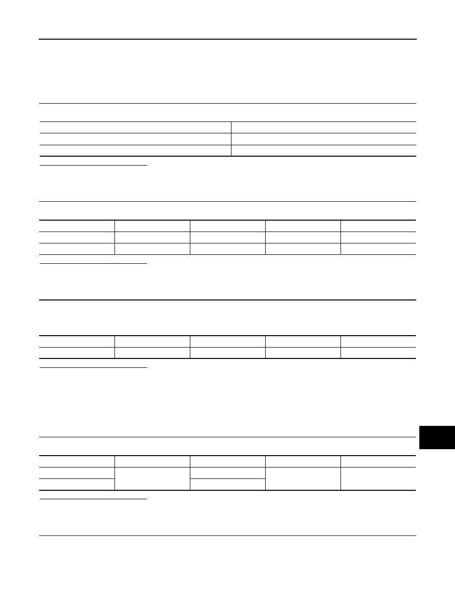
Power source
Fuse No.
Battery
34
Ignition switch ACC or ON
19
Signal name
Connector No.
Terminal No.
Ignition switch position
Value (Approx.)
Battery power supply
M201
19
OFF
Battery voltage
ACC power supply
M201
7
ACC
Battery voltage
Signal name
Connector No.
Terminal No.
Ignition switch position
Continuity
Ground
M201
20
OFF
Existed
Signal name
Connector No.
Terminal No.
Ignition switch position
Value (Approx.)
Inverter VCC
M194
2
ACC
8.8 V
Signal VCC
3
AV-102
< DTC/CIRCUIT DIAGNOSIS >
[WITHOUT NAVIGATION]
POWER SUPPLY AND GROUND CIRCUIT
4.
Check continuity between front display unit harness connector and ground.
Is the inspection result normal?
YES
>> GO TO 3.
NO
>> Repair harness or connector.
3.
CHECK POWER SUPPLY CIRCUIT (AV CONTROL UNIT SIDE)
1.
Connect the AV control unit harness connector.
2.
Turn ignition switch ACC.
3.
Check voltage between AV control unit harness connector and ground.
Is the inspection result normal?
YES
>> INSPECTION END
NO
>> Replacement of AV control unit.
4.
CHECK GROUND CIRCUIT
1.
Turn ignition switch OFF.
2.
Disconnect front display unit connector.
3.
Check continuity between front display unit harness connectors and ground.
Is the inspection result normal?
YES
>> INSPECTION END
NO
>> Repair harness or connector.
BOSE AMP.
BOSE AMP. : Diagnosis Procedure
INFOID:0000000005528980
1.
CHECK FUSE
Check for blown fuses.
Is the inspection result normal?
YES
>> GO TO 2.
NO
>> Be sure to eliminate cause of malfunction before installing new fuse.
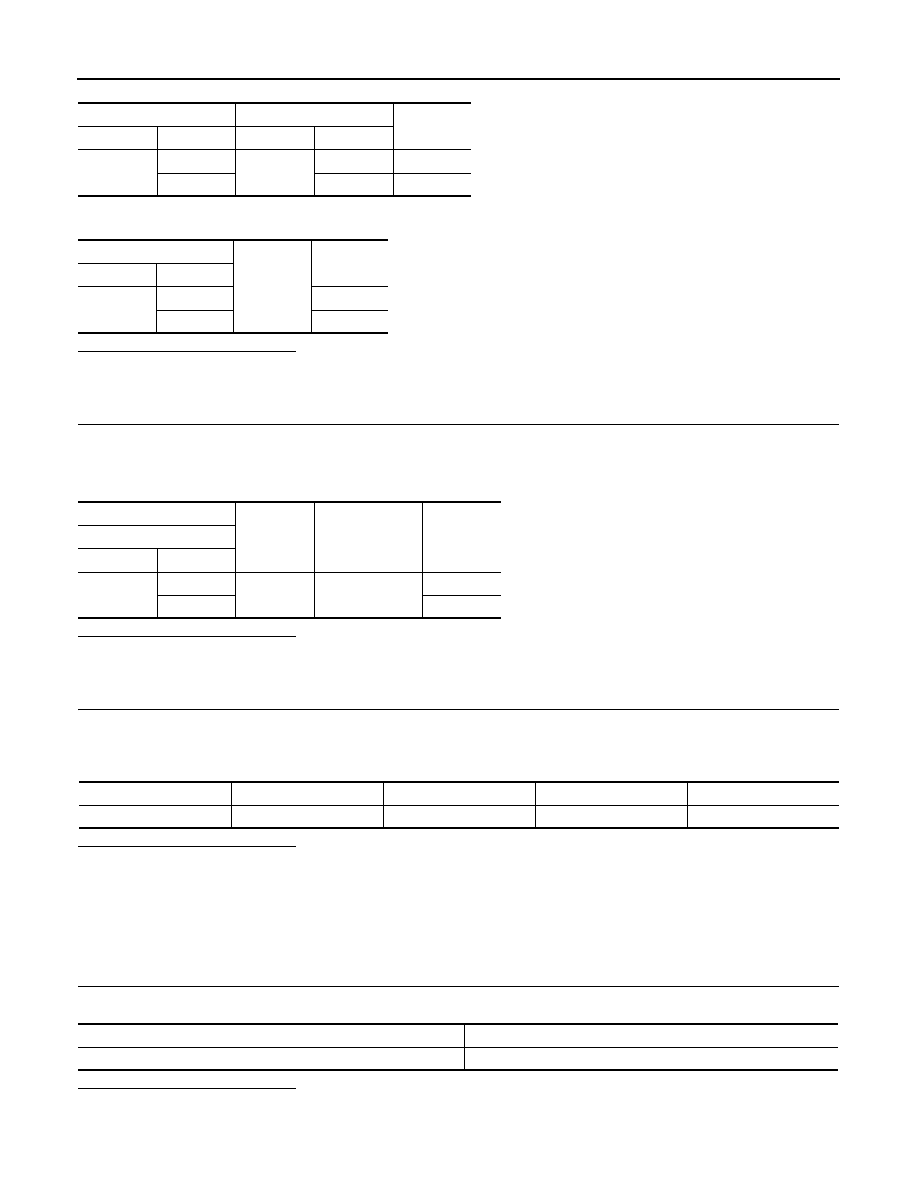
Front display unit
AV control unit
Continuity
Connector
Terminal
Connector
Terminal
M194
2
M202
48
Existed
3
36
Existed
Front display unit
Ground
Continuity
Connector
Terminal
M194
2
Not existed
3
Not existed
(+)
(
−
)
Ignition switch
position
Voltage
(Approx.)
AV control unit
Connector
Terminal
M202
48
Ground
ACC
8.8 V
36
8.8 V
Signal name
Connector No.
Terminal No.
Ignition switch position
Continuity
Ground
M194
1
OFF
Existed
Power source
Fuse No.
Battery
8
AV
POWER SUPPLY AND GROUND CIRCUIT
AV-103
< DTC/CIRCUIT DIAGNOSIS >
[WITHOUT NAVIGATION]
C
D
E
F
G
H
I
J
K
L
M
B
A
O
P
2.
CHECK POWER SUPPLY CIRCUIT
Check voltage between BOSE amp. harness connector and ground.
Is the inspection result normal?
YES
>> GO TO 3.
NO
>> Check harness between BOSE amp. and fuse.
3.
CHECK GROUND CIRCUIT
1.
Turn ignition switch OFF.
2.
Disconnect BOSE amp. connector.
3.
Check continuity between BOSE amp. harness connector and ground.
Is the inspection result normal?
YES
>> INSPECTION END
NO
>> Repair harness or connector.
SATELLITE RADIO TUNER
SATELLITE RADIO TUNER : Diagnosis Procedure
INFOID:0000000005246809
1.
CHECK FUSE
Check for blown fuses.
Is the inspection result normal?
YES
>> GO TO 2.
NO
>> Be sure to eliminate cause of malfunction before installing new fuse.
2.
CHECK POWER SUPPLY CIRCUIT
Check voltage between satellite radio tuner harness connector and ground.
Is the inspection result normal?
YES
>> INSPECTION END
NO
>> Check harness between satellite radio tuner and fuse.
TEL ADAPTER UNIT
TEL ADAPTER UNIT : Diagnosis Procedure
INFOID:0000000005246811
1.
CHECK FUSE
Check for blown fuses.
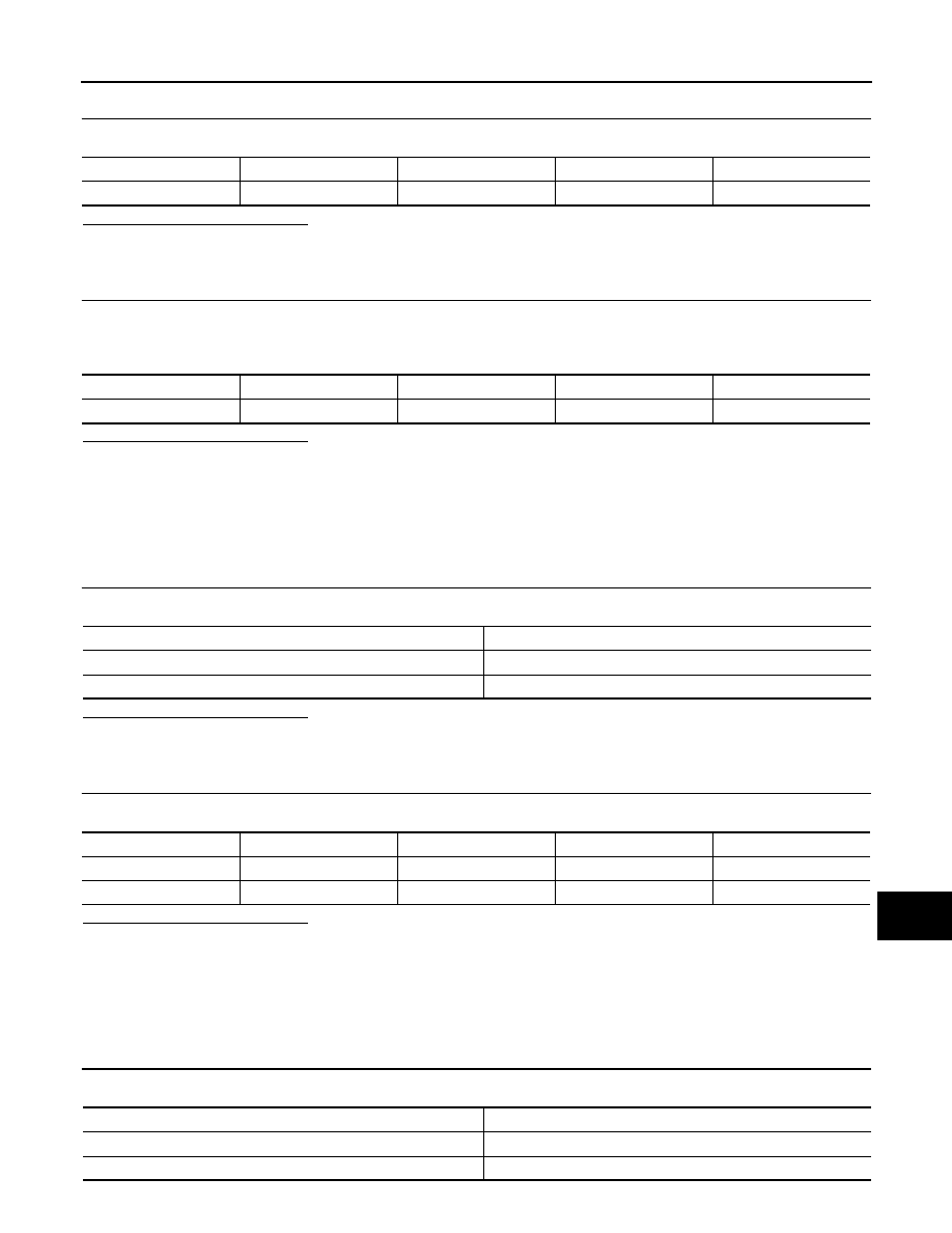
Signal name
Connector No.
Terminal No.
Ignition switch position
Value (Approx.)
Battery power supply
B42
11
OFF
Battery voltage
Signal name
Connector No.
Terminal No.
Ignition switch position
Continuity
Ground
B42
12
OFF
Existed
Power source
Fuse No.
Battery
34
Ignition switch ACC or ON
19
Signal name
Connector No.
Terminal No.
Ignition switch position
Value (Approx.)
Battery power supply
B236
12
OFF
Battery voltage
ACC power supply
B236
16
ACC
Battery voltage
Power source
Fuse No.
Battery
34
Ignition switch ACC or ON
19
AV-104
< DTC/CIRCUIT DIAGNOSIS >
[WITHOUT NAVIGATION]
POWER SUPPLY AND GROUND CIRCUIT
Is the inspection result normal?
YES
>> GO TO 2.
NO
>> Be sure to eliminate cause of malfunction before installing new fuse.
2.
CHECK POWER SUPPLY CIRCUIT
Check voltage between TEL adapter unit harness connector and ground.
Is the inspection result normal?
YES
>> GO TO 3.
NO
>> Check harness between TEL adapter unit and fuse.
3.
CHECK GROUND CIRCUIT
1.
Turn ignition switch OFF.
2.
Disconnect TEL adapter unit connector.
3.
Check continuity between TEL adapter unit harness connector and ground.
Is the inspection result normal?
YES
>> INSPECTION END
NO
>> Repair harness or connector.
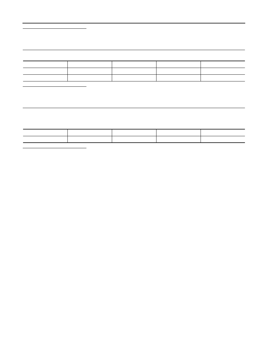
Signal name
Connector No.
Terminal No.
Ignition switch position
Value (Approx.)
Battery power supply
B87
1
OFF
Battery voltage
ACC power supply
B87
2
ACC
Battery voltage
Signal name
Connector No.
Terminal No.
Ignition switch position
Continuity
Ground
B87
4
OFF
Existed
Нет комментариевНе стесняйтесь поделиться с нами вашим ценным мнением.
Текст