Infiniti FX35, FX50 (S51). Manual — part 579
FRONT FINAL DRIVE ASSEMBLY
DLN-151
< UNIT REMOVAL AND INSTALLATION >
[FRONT FINAL DRIVE: F160A]
C
E
F
G
H
I
J
K
L
M
A
B
DLN
N
O
P
• Tighten mounting bolts in the order described below when install-
ing front final drive assembly: side of gear carrier (1), upper side of
gear carrier (2), part of carrier cover (3), lower part of gear carrier
(4).
CAUTION:
Align the mating faces of gear carrier and oil pan for installa-
tion.
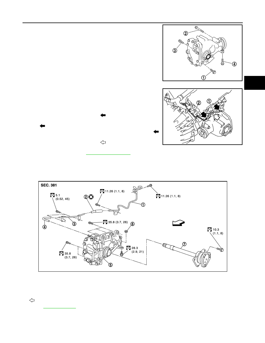
• Install breather hose (1) and tube (2) as shown in the figure.
CAUTION:
Make sure there are no pinched or restricted areas on the
breather hose caused by bending or winding when installing
it.
- Make sure the paint mark facing up (
).
- Securely install the hose until it seats the rounded portion of the
tube. (
) (front final drive assembly side).
- Securely install the hose until it to paint mark of the tube. (
)
(vehicle rear side).
- Face the bend of the breather hose (
) to the engine.
• When oil leaks while removing final drive assembly, check oil level
after the installation. Refer to
VK50VE
VK50VE : Exploded View
INFOID:0000000005249195
VK50VE : Removal and Installation
INFOID:0000000005249196
REMOVAL
PDIA0839J
JSDIA0018ZZ
1.
Breather tube
2.
Breather hose
3.
Breather tube
4.
Breather hose
5.
Front final drive assembly
6.
Bushing
7.
Side shaft
: Vehicle front
Refer to
JSDIA0825GB

DLN-152
< UNIT REMOVAL AND INSTALLATION >
[FRONT FINAL DRIVE: F160A]
FRONT FINAL DRIVE ASSEMBLY
1.
Remove engine assembly from the vehicle. Refer to
EM-196, "Removal and Installation"
.
2.
Separate engine assembly and suspension member.
3.
Remove air breather hose and tube.
4.
Remove side shaft. Refer to
.
5.
Remove final drive assembly mounting bolts with power tool and separate front final drive assembly from
engine.
INSTALLATION
Note the following, install in the reverse order of removal.
• When installing the side shaft, apply multi-purpose grease to contact surface of side shaft and side shaft oil
seal.
• Tighten mounting bolts in the order described below when install-
ing front final drive assembly: side of gear carrier (1), lower part of
gear carrier (2).
CAUTION:
Align the mating faces of gear carrier and oil pan for installa-
tion.
• When installing breather hose and tube, refer to the figure.
CAUTION:
Make sure there are no pinched or restricted areas on the
breather hose caused by bending or winding when installing
it.
- Securely install the hose until it seats the spool position (1) of the
tube (front final drive assembly side).
- Be sure to insert transfer air breather hose into breather tube until
hose end reaches the breather tube bracket (2) (vehicle rear side).
CAUTION:
Never reuse air breather hose (vehicle rear side).
• When oil leaks while removing final drive assembly, check oil level
after the installation. Refer to
JPDID0222ZZ
JPDID0223ZZ
SIDE SHAFT
DLN-153
< UNIT DISASSEMBLY AND ASSEMBLY >
[FRONT FINAL DRIVE: F160A]
C
E
F
G
H
I
J
K
L
M
A
B
DLN
N
O
P
UNIT DISASSEMBLY AND ASSEMBLY
SIDE SHAFT
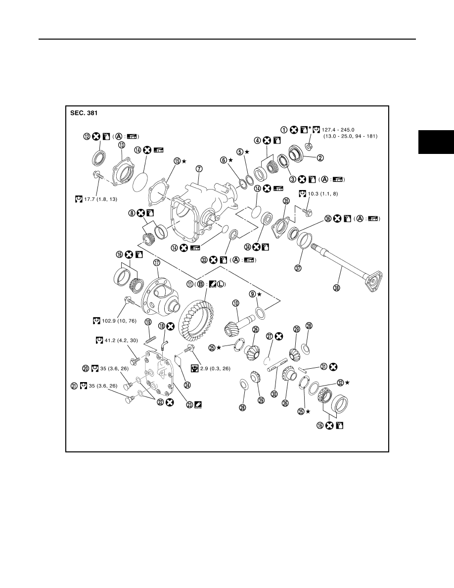
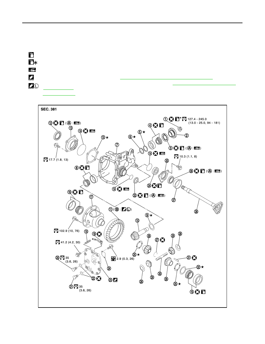
Exploded View
INFOID:0000000005249197
VQ35HR
JSDIA0020GB
1.
Drive pinion lock nut
2.
Companion flange
3.
Front oil seal
4.
Pinion front bearing
5.
Drive pinion bearing adjusting wash-
er
6.
Drive pinion adjusting washer
7.
Gear carrier
8.
Pinion rear bearing
9.
Pinion height adjusting washer
10. Drive pinion
11.
Drive gear
12. Side oil seal (right side)
13. Side retainer
14. O-ring
15. Side bearing adjusting shim
16. Side bearing
17. Differential case
18. Breather connector
19. Dowel pin
20. Filler plug
21. Drain plug
22. Gasket
23. Carrier cover
24. Gear oil defense
25. Side gear thrust washer
26. Side gear
27. Circular clip
28. Pinion mate thrust washer
29. Pinion mate gear
30. Pinion mate shaft
DLN-154
< UNIT DISASSEMBLY AND ASSEMBLY >
[FRONT FINAL DRIVE: F160A]
SIDE SHAFT
VK50VE
31. Lock pin
32. Side bearing adjusting washer
33. Side oil seal (left side)
34. Side shaft bearing
35. Extension tube retainer
36. Side shaft oil seal
37. Dust seal
38. Side shaft
A:
Oil seal lip
B:
Screw hole
: Apply gear oil.
: Apply anti-corrosion oil.
: Apply multi-purpose grease.
: Apply Genuine Silicone RTV or equivalent. Refer to
GI-16, "Recommended Chemical Products and Sealants"
.
:
Apply Genuine Medium Strength Thread Locking Sealant or equivalent. Refer to
GI-16, "Recommended Chemical Prod-
.
Refer to
for symbols not described above.
JPDID0225GB
1.
Drive pinion lock nut
2.
Companion flange
3.
Front oil seal
4.
Pinion front bearing
5.
Drive pinion bearing adjusting wash-
er
6.
Drive pinion adjusting washer
Нет комментариевНе стесняйтесь поделиться с нами вашим ценным мнением.
Текст