Infiniti FX35, FX50 (S51). Manual — part 56
ADP-216
< REMOVAL AND INSTALLATION >
AUTOMATIC DRIVE POSITIONER CONTROL UNIT
AUTOMATIC DRIVE POSITIONER CONTROL UNIT
Exploded View
INFOID:0000000005249815
.
Removal and Installation
INFOID:0000000005249816
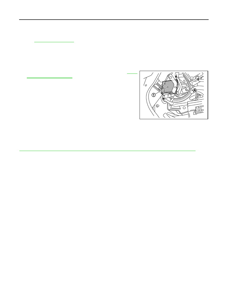
REMOVAL
CAUTION:
When removing and installing, use shop cloths to protect parts from damage.
1.
Remove the instrument driver lower panel. Refer to
2.
Remove the screws (A).
3.
Remove automatic drive positioner control unit (1).
INSTALLATION
Install in the reverse order of removal.
CAUTION:
Be sure to clump the harness to the right place.
NOTE:
After installing the driver seat, perform additional service when removing battery negative terminal. Refer to
ADP-8, "ADDITIONAL SERVICE WHEN REMOVING BATTERY NEGATIVE TERMINAL : Description"
.
JMJIA0198ZZ
SEAT MEMORY SWITCH
ADP-217
< REMOVAL AND INSTALLATION >
C
D
E
F
G
H
I
K
L
M
A
B
ADP
N
O
P
SEAT MEMORY SWITCH
Exploded View
INFOID:0000000005249817
Removal and Installation
INFOID:0000000005249818
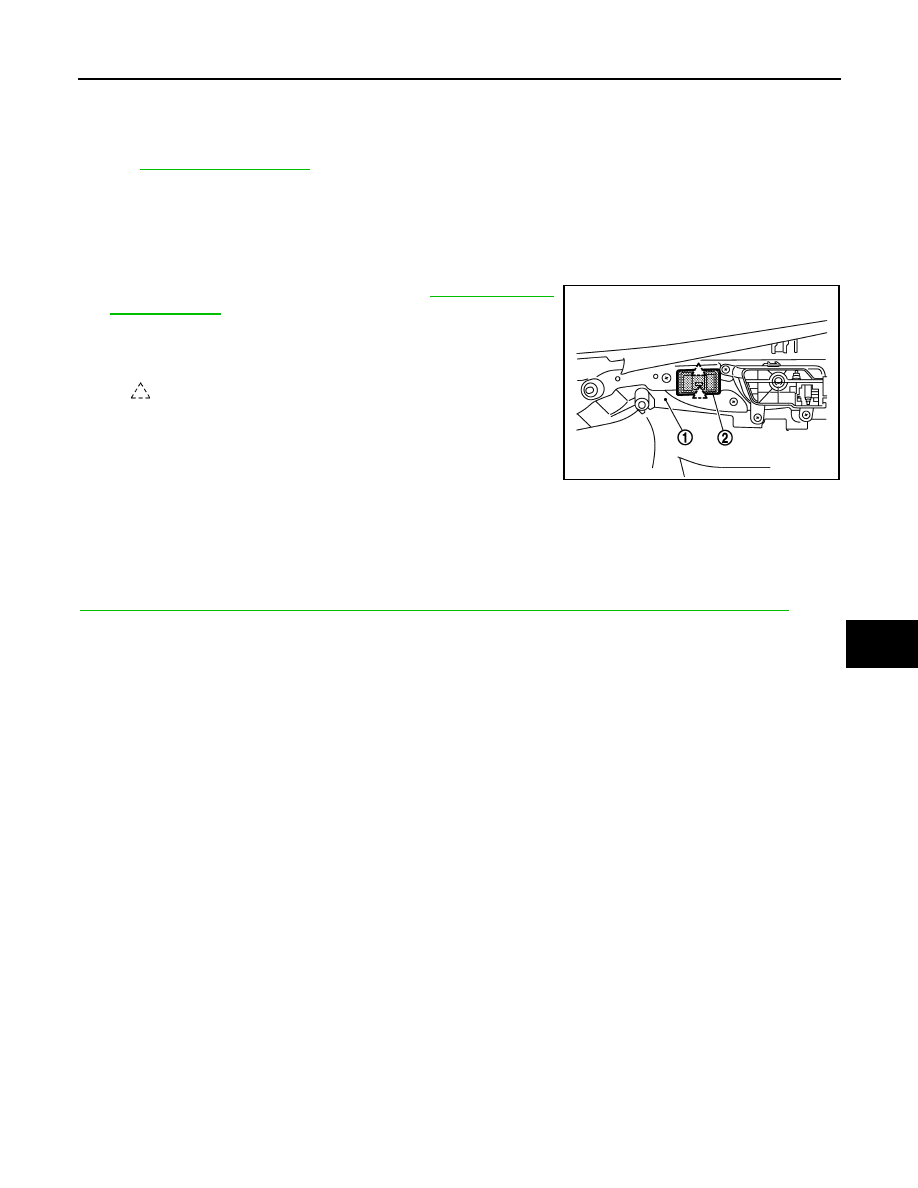
REMOVAL
CAUTION:
When removing and installing, use shop cloths to protect parts from damage.
1.
Remove the front door finisher (1). Refer to
2.
Press pawls and remove seat memory switch (2) from front door
finisher (1).
INSTALLATION
Install in the reverse order of removal.
CAUTION:
Be sure to clump the harness to the right place.
NOTE:
After installing the driver seat, perform additional service when removing battery negative terminal. Refer to
ADP-8, "ADDITIONAL SERVICE WHEN REMOVING BATTERY NEGATIVE TERMINAL : Description"
.
:
Pawl
JMJIA1474ZZ
ADP-218
< REMOVAL AND INSTALLATION >
POWER SEAT SWITCH
POWER SEAT SWITCH
Exploded View
INFOID:0000000005249819
Removal and Installation
INFOID:0000000005249820
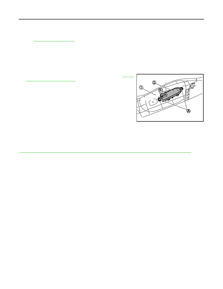
REMOVAL
CAUTION:
When removing and installing, use shop cloths to protect parts from damage.
1.
Remove the seat cushion outer finisher (1). Refer to
.
2.
Remove the screws (A).
3.
Remove the power seat switch (2) from the seat cushion outer
finisher (1).
INSTALLATION
Install in the reverse order of removal.
CAUTION:
Be sure to clump the harness to the right place.
NOTE:
After installing the driver seat, perform additional service when removing battery negative terminal. Refer to
ADP-8, "ADDITIONAL SERVICE WHEN REMOVING BATTERY NEGATIVE TERMINAL : Description"
.
JMJIA0319JP
TILT&TELESCOPIC SWITCH
ADP-219
< REMOVAL AND INSTALLATION >
C
D
E
F
G
H
I
K
L
M
A
B
ADP
N
O
P
TILT&TELESCOPIC SWITCH
Exploded View
INFOID:0000000005249821
.
Removal and Installation
INFOID:0000000005249822
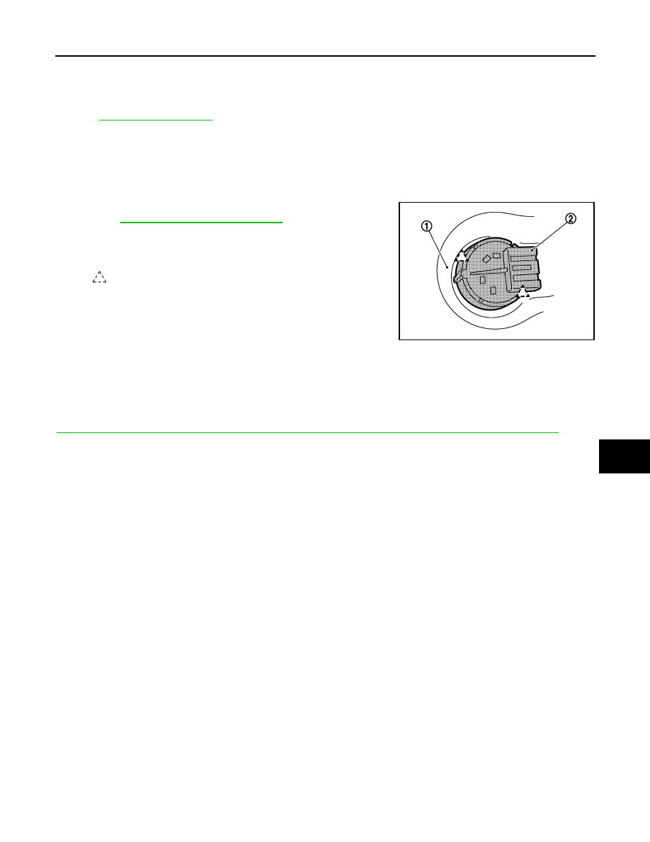
REMOVAL
CAUTION:
When removing and installing, use shop cloths to protect parts from damage.
1.
Remove the steering column mask (1).
Refer to
IP-12, "Removal and Installation"
.
2.
Press pawls and remove tilt & telescopic switch (2) from the
steering column mask (1).
INSTALLATION
Install in the reverse order of removal.
CAUTION:
Be sure to clump the harness to the right place.
NOTE:
After installing the driver seat, perform additional service when removing battery negative terminal. Refer to
ADP-8, "ADDITIONAL SERVICE WHEN REMOVING BATTERY NEGATIVE TERMINAL : Description"
.
:
Pawl
JMJIA1467ZZ
Нет комментариевНе стесняйтесь поделиться с нами вашим ценным мнением.
Текст