Infiniti FX35, FX50 (S51). Manual — part 55

ADP-212
< SYMPTOM DIAGNOSIS >
NORMAL OPERATING CONDITION
NORMAL OPERATING CONDITION
Description
INFOID:0000000005249809
The following symptoms are normal operations, and they do not indicate a malfunction.
Symptom
Cause
Action to take
Reference page
Entry/exit assist function and
seat synchronization do not op-
erate.
No initialization has been performed.
Perform initialization.
Entry/exit assist function is disabled.
NOTE:
The entry/exit assist function and seat
synchronization function are disabled be-
fore delivery (initial setting).
Change the settings.
Entry assist function does not op-
erate.
Manual operation with power seat switch
was performed after exit assist function
execution.
Perform the memory
function.
Seat synchronization function
does not operate.
Either the entry/exit assist function (seat)
or the entry/exit assist function (steering)
is disabled.
Enable both functions.
The synchronization function will not op-
erate if the steering (tilt, telescopic) or the
door mirror moves to the operating end
while the seat synchronization function is
operating.
Perform the memory
function
or
drive the vehicle at
more than
7 km/h (4 MPH).
Seat adjustment load has exceed any of
the volumes below.
• Seat sliding: 76 mm
• Seat reclining: 9.1 degrees
• Seat lifting (rear): 20 mm
—
—
Lumbar support does not per-
form memory operation.
The lumbar support system are con-
trolled independently with no link to the
automatic drive positioner system.
—
Lumbar support system:
Memory function, entry/exit as-
sist function, seat synchroniza-
tion function, or Intelligent Key
interlock function does not oper-
ate.
The operating conditions are not fulfilled.
Fulfill the operation
conditions.
Memory function:
Exit assist function:
Entry assist function:
Seat synchronization
function:
Intelligent Key interlock
function:
PRECAUTIONS
ADP-213
< PRECAUTION >
C
D
E
F
G
H
I
K
L
M
A
B
ADP
N
O
P
PRECAUTION
PRECAUTIONS
Precaution for Supplemental Restraint System (SRS) "AIR BAG" and "SEAT BELT
PRE-TENSIONER"
INFOID:0000000005249810
The Supplemental Restraint System such as “AIR BAG” and “SEAT BELT PRE-TENSIONER”, used along
with a front seat belt, helps to reduce the risk or severity of injury to the driver and front passenger for certain
types of collision. This system includes seat belt switch inputs and dual stage front air bag modules. The SRS
system uses the seat belt switches to determine the front air bag deployment, and may only deploy one front
air bag, depending on the severity of a collision and whether the front occupants are belted or unbelted.
Information necessary to service the system safely is included in the “SRS AIR BAG” and “SEAT BELT” of this
Service Manual.
WARNING:
• To avoid rendering the SRS inoperative, which could increase the risk of personal injury or death in
the event of a collision which would result in air bag inflation, all maintenance must be performed by
an authorized NISSAN/INFINITI dealer.
• Improper maintenance, including incorrect removal and installation of the SRS, can lead to personal
injury caused by unintentional activation of the system. For removal of Spiral Cable and Air Bag
Module, see the “SRS AIR BAG”.
• Do not use electrical test equipment on any circuit related to the SRS unless instructed to in this
Service Manual. SRS wiring harnesses can be identified by yellow and/or orange harnesses or har-
ness connectors.
PRECAUTIONS WHEN USING POWER TOOLS (AIR OR ELECTRIC) AND HAMMERS
WARNING:
• When working near the Air Bag Diagnosis Sensor Unit or other Air Bag System sensors with the
ignition ON or engine running, DO NOT use air or electric power tools or strike near the sensor(s)
with a hammer. Heavy vibration could activate the sensor(s) and deploy the air bag(s), possibly
causing serious injury.
• When using air or electric power tools or hammers, always switch the ignition OFF, disconnect the
battery, and wait at least 3 minutes before performing any service.
Service
INFOID:0000000005249811
• When removing or installing various parts, place a cloth or padding onto the vehicle body to prevent
scratches.
• Handle trim, molding, instruments, grille, etc. carefully during removing or installing. Be careful not to oil or
damage them.
• Apply sealing compound where necessary when installing parts.
• When applying sealing compound, be careful that the sealing compound does not protrude from parts.
• When replacing any metal parts (for example body outer panel, members, etc.), be sure to take rust preven-
tion measures.
Work
INFOID:0000000005249812
• When removing or disassembling each component, be careful not to damage or deform it. If a component
may be subject to interference, be sure to protect it with a shop cloth.
• When removing (disengaging) components with a screwdriver or similar tool, be sure to wrap the component
with a shop cloth or vinyl tape to protect it.
• Protect the removed parts with a shop cloth and keep them.
• Replace a deformed or damaged clip.
• If a part is specified as a non-reusable part, always replace it with new one.
• Be sure to tighten bolts and nuts securely to the specified torque.
• After re-installation is completed, be sure to check that each part works normally.
• Follow the steps below to clean components.
- Water soluble foul: Dip a soft cloth into lukewarm water, and wring the water out of the cloth to wipe the
fouled area.
Then rub with a soft and dry cloth.
ADP-214
< PRECAUTION >
PRECAUTIONS
- Oily foul: Dip a soft cloth into lukewarm water with mild detergent (concentration: within 2 to 3%), and wipe
the fouled area.
Then dip a cloth into fresh water, and wring the water out of the cloth to wipe the detergent off. Then rub with
a soft and dry cloth.
• Do not use organic solvent such as thinner, benzene, alcohol, and gasoline.
• For genuine leather seats, use a genuine leather seat cleaner.
DRIVER SEAT CONTROL UNIT
ADP-215
< REMOVAL AND INSTALLATION >
C
D
E
F
G
H
I
K
L
M
A
B
ADP
N
O
P
REMOVAL AND INSTALLATION
DRIVER SEAT CONTROL UNIT
Exploded View
INFOID:0000000005249813
.
Removal and Installation
INFOID:0000000005249814
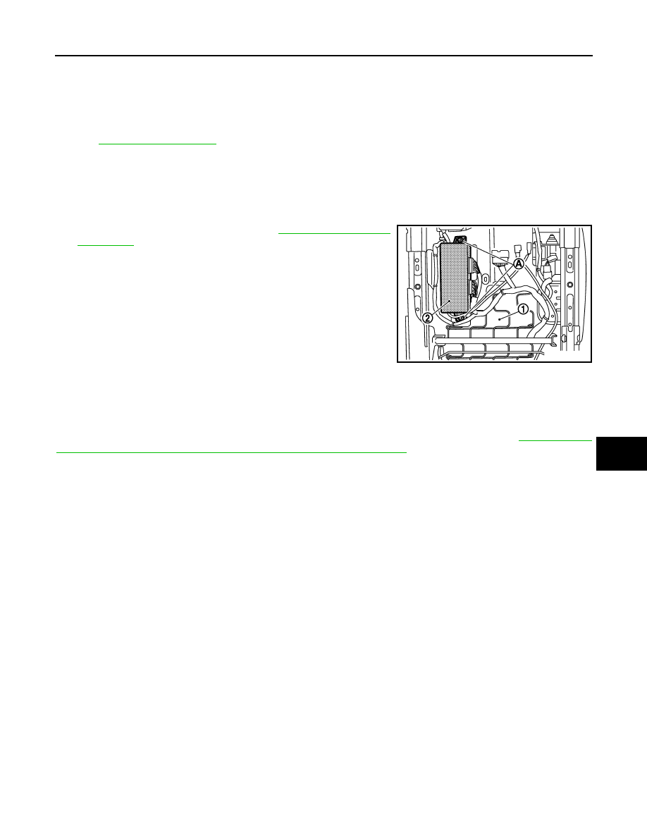
REMOVAL
CAUTION:
When removing and installing, use shop cloths to protect parts from damage.
1.
Remove the driver seat (1). Refer to
.
2.
Remove the mounting bolts (A).
3.
Remove driver seat control unit (2).
INSTALLATION
Install in the reverse order of removal.
CAUTION:
Be sure to clump the harness to the right place.
NOTE:
After installing the driver seat, perform additional service when replacing control unit. Refer to
TIONAL SERVICE WHEN REPLACING CONTROL UNIT : Description"
JMJIA1669ZZ
Нет комментариевНе стесняйтесь поделиться с нами вашим ценным мнением.
Текст