Infiniti FX35, FX50 (S51). Manual — part 375
CCS-320
< DTC/CIRCUIT DIAGNOSIS >
[DCA]
POWER SUPPLY AND GROUND CIRCUIT
Is the inspection result normal?
YES
>> GO TO 3.
NO
>> Repair the accelerator pedal actuator power supply circuit.
3.
CHECK ACCELERATOR PEDAL ACTUATOR GROUND CIRCUIT
Check for continuity between accelerator pedal actuator harness connector and ground.
Is the inspection result normal?
YES
>> INSPECTION END
NO
>> Repair the accelerator pedal actuator ground circuit.
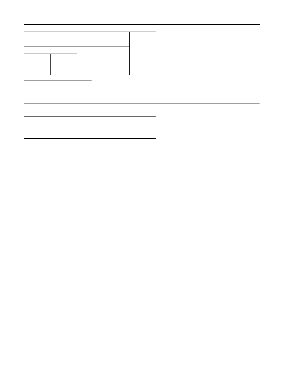
Terminals
Condition
Voltage
(+)
(–)
Accelerator pedal actuator
Ground
Ignition
switch
Connector
Terminal
E115
2
OFF
Battery volt-
age
1
ON
Accelerator pedal actuator
Ground
Continuity
Connector
Terminal
E115
4
Existed
CCS
ICC WARNING CHIME CIRCUIT
CCS-321
< DTC/CIRCUIT DIAGNOSIS >
[DCA]
C
D
E
F
G
H
I
J
K
L
M
B
N
P
A
ICC WARNING CHIME CIRCUIT
Description
INFOID:0000000005501988
• The ICC sensor integrated unit transmits the buzzer output signal to the brake booster control unit via ITS
communication.
• The brake booster control unit outputs the buzzer output signal to the ICC warning chime.
• A warning chime sounds when the system is canceled or when the vehicle distance from the vehicle ahead
is too close.
Component Function Check
INFOID:0000000005501989
1.
ICC WARNING CHIME OPERATION INSPECTION
1.
Select the active test item “ICC BUZZER” of “ICC” with CONSULT-III.
2.
Check if the ICC warning chime sounds when operating each test item.
Does the ICC warning chime sound?
YES
>> The ICC warning chime circuit is normal.
NO
>> Refer to
CCS-321, "Diagnosis Procedure"
Diagnosis Procedure
INFOID:0000000005501990
1.
CHECK ICC WARNING CHIME POWER SUPPLY CIRCUIT
1.
Turn ignition switch OFF.
2.
Disconnect the ICC warning chime connector.
3.
Turn ignition switch ON.
4.
Check voltage between ICC warning chime harness connector and ground.
Is the inspection result normal?
YES
>> GO TO 2.
NO
>> Repair the harnesses or connectors.
2.
CHECK ICC WARNING CHIME SIGNAL CIRCUIT
1.
Turn ignition switch OFF.
2.
Disconnect brake booster control unit connector.
3.
Check for continuity between the ICC warning chime harness connector and brake booster control unit
harness connector.
Is the inspection result normal?
YES
>> GO TO 3.
NO
>> Repair the harnesses or connectors.
3.
CHECK ICC WARNING CHIME SIGNAL CIRCUIT SHORT
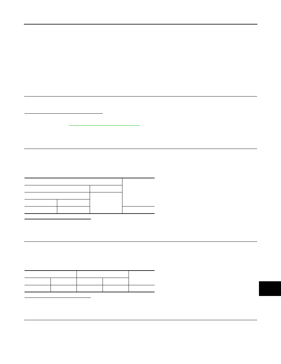
Check for continuity between ICC warning chime harness connector and ground.
Terminals
Voltage
(Approx.)
(+)
(–)
ICC warning chime
Ground
Connector
Terminal
M17
1
Battery voltage
ICC warning chime
Brake booster control unit
Continuity
Connector
Terminal
Connector
Terminal
M17
3
B250
21
Existed
CCS-322
< DTC/CIRCUIT DIAGNOSIS >
[DCA]
ICC WARNING CHIME CIRCUIT
Is the inspection result normal?
YES
>> GO TO 4.
NO
>> Repair the harnesses or connectors.
4.
CHECK ICC WARNING CHIME
Check the ICC warning chime. Refer to
CCS-322, "Component Inspection"
.
Is the inspection result normal?
YES
>> Replace the brake booster control unit.
NO
>> Replace the ICC warning chime.
Component Inspection
INFOID:0000000005501991
1.
ICC WARNING CHIME INSPECTION
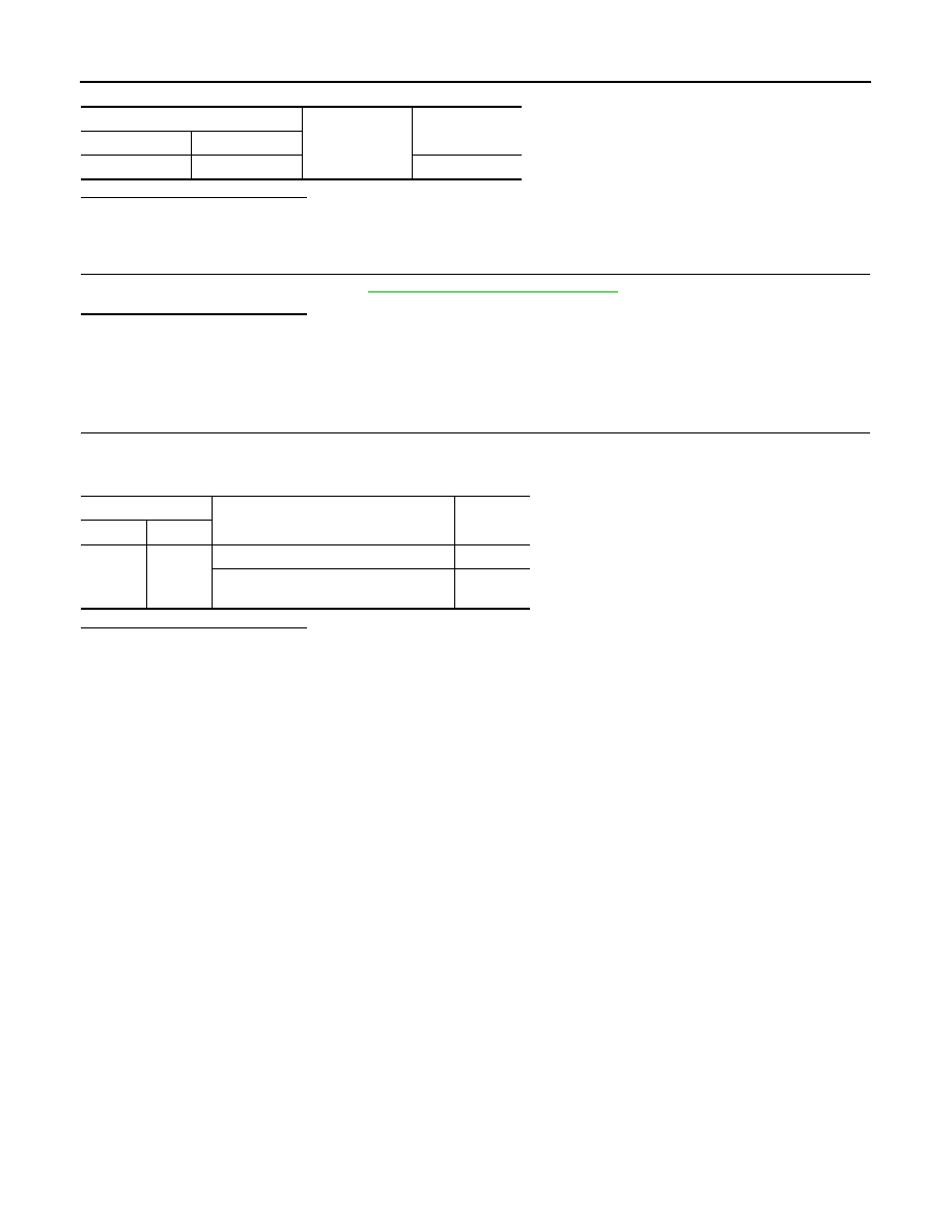
Apply the battery voltage between ICC warning chime terminals, and then check if the ICC warning chime
sounds.
Is the inspection result normal?
YES
>> INSPECTION END
NO
>> Replace the ICC warning chime.
ICC warning chime
Ground
Continuity
Connector
Terminal
M17
3
Not existed
Terminal
Condition
Warning
chime
(+)
(–)
1
3
When the battery voltage is applied
Sounds
When the battery voltage is not applied
Does not
sound
CCS
ICC SENSOR INTEGRATED UNIT
CCS-323
< ECU DIAGNOSIS INFORMATION >
[DCA]
C
D
E
F
G
H
I
J
K
L
M
B
N
P
A
ECU DIAGNOSIS INFORMATION
ICC SENSOR INTEGRATED UNIT
Reference Value
INFOID:0000000005501992
VALUES ON THE DIAGNOSIS TOOL
Monitor item
Condition
Value/Status
MAIN SW
Ignition switch ON
When MAIN switch is pressed
On
When MAIN switch is not pressed
Off
SET/COAST SW
Ignition switch ON
When SET/COAST switch is pressed
On
When SET/COAST switch is not pressed
Off
CANCEL SW
Ignition switch ON
When CANCEL switch is pressed
On
When CANCEL switch is not pressed
Off
RESUME/ACC SW
Ignition switch ON
When RESUME/ACCELERATE switch is pressed
On
When RESUME/ACCELERATE switch is not pressed
Off
DISTANCE SW
Ignition switch ON
When DISTANCE switch is pressed
On
When DISTANCE switch is not pressed
Off
CRUISE OPE
Drive the vehicle and operate
the ICC system.
When ICC system is controlling
On
When ICC system is not controlling
Off
BRAKE SW
Ignition switch ON
When brake pedal is depressed
Off
When brake pedal is not depressed
On
STOP LAMP SW
Ignition switch ON
When brake pedal is depressed
On
When brake pedal is not depressed
Off
IDLE SW
Engine running
Idling
On
Except idling (depress accelerator pedal)
Off
SET DISTANCE
• Start the engine and turn the
ICC system ON.
• Press the DISTANCE
switch to change the vehi-
cle-to-vehicle distance set-
ting.
When set to “long”
Long
When set to “middle”
Mid
When set to “short”
Short
CRUISE LAMP
Start the engine and press
MAIN switch.
ICC system ON
(MAIN switch indicator ON)
On
ICC system OFF
(MAIN switch indicator OFF)
Off
OWN VHCL
Start the engine and press
MAIN switch.
ICC system ON
(Own vehicle indicator ON)
On
ICC system OFF
(Own vehicle indicator OFF)
Off
VHCL AHEAD
Drive the vehicle and activate
the vehicle-to-vehicle distance
control mode.
When a vehicle ahead is detected (vehicle ahead de-
tection indicator ON)
On
When a vehicle ahead is not detected (vehicle ahead
detection indicator OFF)
Off
ICC WARNING
Start the engine and press the
MAIN switch.
When ICC system is malfunctioning
(ICC system warning lamp ON)
On
When ICC system is normal
(ICC system warning lamp OFF)
Off
VHCL SPEED SE
While driving
Value of vehicle
speed signal
(wheel speed)
Нет комментариевНе стесняйтесь поделиться с нами вашим ценным мнением.
Текст