Infiniti FX35, FX50 (S51). Manual — part 374

CCS-316
< DTC/CIRCUIT DIAGNOSIS >
[DCA]
U1010 CONTROL UNIT (CAN)
U1010 CONTROL UNIT (CAN)
ICC SENSOR INTEGRATED UNIT
ICC SENSOR INTEGRATED UNIT : Description
INFOID:0000000005501977
• CAN controller controls the communication of CAN communication signal and the error detection.
• CAN controller controls the communication of ITS communication signal and the error detection.
ICC SENSOR INTEGRATED UNIT : DTC Logic
INFOID:0000000005501978
DTC DETECTION LOGIC
ICC SENSOR INTEGRATED UNIT : Diagnosis Procedure
INFOID:0000000005501979
1.
PERFORM DTC CONFIRMATION PROCEDURE
1.
Turn the DCA system ON.
2.
Perform “All DTC Reading” with CONSULT-III.
3.
Check if the “U1010” is detected as the current malfunction in self-diagnosis results of “ICC”.
Is “U1010” detected as the current malfunction?
YES
>> Replace the ICC sensor integrated unit.
NO
>> INSPECTION END
ICC SENSOR INTEGRATED UNIT : Special Repair Requirement
INFOID:0000000005501980
DESCRIPTION
Perform the action test after adjusting the laser beam aiming of ICC sensor integrated unit when the following
operation is performed.
• Removal and installation of ICC sensor integrated unit
• Replacement of ICC sensor integrated unit
SPECIAL REPAIR REQUIREMENT
1.
LASER BEAM AIMING ADJUSTMENT OF ICC SENSOR INTEGRATED UNIT
Adjust the laser beam aiming of the ICC sensor integrated unit. Refer to
>> GO TO 2.
2.
CHECK DCA SYSTEM
1.
Erase the “self-diagnosis results”, and then perform “All DTC Reading” again after performing the action
test. (Refer to
CCS-191, "ACTION TEST : Description"
for action test.)
2.
Check that the DCA system is normal.
>> WORK END
ACCELERATOR PEDAL ACTUATOR
ACCELERATOR PEDAL ACTUATOR : Description
INFOID:0000000005501981
CAN controller controls the communication of ITS communication signal and the error detection.
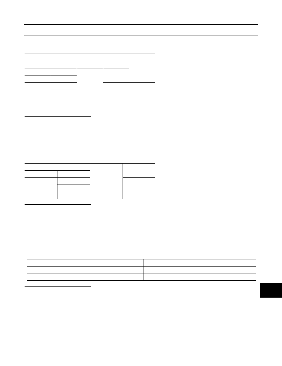
DTC
(On board
display)
Trouble diagnosis name
DTC detecting condition
Possible causes
U1010
(110)
CONTROL UNIT (CAN)
If ICC sensor integrated unit detects malfunc-
tion by CAN controller initial diagnosis
ICC sensor integrated unit

CCS
U1010 CONTROL UNIT (CAN)
CCS-317
< DTC/CIRCUIT DIAGNOSIS >
[DCA]
C
D
E
F
G
H
I
J
K
L
M
B
N
P
A
ACCELERATOR PEDAL ACTUATOR : DTC Logic
INFOID:0000000005501982
DTC DETECTION LOGIC
ACCELERATOR PEDAL ACTUATOR : Diagnosis Procedure
INFOID:0000000005501983
1.
PERFORM DTC CONFIRMATION PROCEDURE
1.
Turn the DCA system ON.
2.
Perform “All DTC Reading” with CONSULT-III.
3.
Check if the DTC “U1010” is detected as the current malfunction in self-diagnosis results of “ACCELE
PEDAL ACT”.
Is “U1010” detected as the current malfunction?
YES
>> Replace the accelerator pedal assembly.
NO
>> INSPECTION END
ACCELERATOR PEDAL ACTUATOR : Special Repair Requirement
INFOID:0000000005501984
DESCRIPTION
The accelerator pedal released position learning is necessary when the following operation is performed.
• Disconnection and connection of accelerator pedal assembly connector
• Replace accelerator pedal assembly
SPECIAL REPAIR REQUIREMENT
1.
ACCELERATOR PEDAL RELEASED POSITION LEARNING
Perform the accelerator pedal released position learning. Refer to
RELEASED POSITION LEARNING : Description"
(VQ35HR) or
RELEASED POSITION LEARNING : Description"
(VK50VE).
>> GO TO 2.
2.
CHECK DCA SYSTEM
1.
Erase the “self-diagnosis results”, and then perform “All DTC Reading” again after performing the action
test. (Refer to
CCS-191, "ACTION TEST : Description"
for action test.)
2.
Check that the DCA system is normal.
>> WORK END
DTC
Trouble diagnosis name
DTC detecting condition
Possible causes
U1010
CONTROL UNIT (CAN)
If accelerator pedal actuator detects malfunc-
tion by CAN controller initial diagnosis.
Accelerator pedal actuator

CCS-318
< DTC/CIRCUIT DIAGNOSIS >
[DCA]
POWER SUPPLY AND GROUND CIRCUIT
POWER SUPPLY AND GROUND CIRCUIT
ICC SENSOR INTEGRATED UNIT
ICC SENSOR INTEGRATED UNIT : Diagnosis Procedure
INFOID:0000000005501985
1.
CHECK FUSES
Check if any of the following fuses are blown:
Is the inspection result normal?
YES
>> GO TO 2.
NO
>> Replace the blown fuse after repairing the affected circuit if a fuse is blown.
2.
CHECK ICC SENSOR INTEGRATED UNIT POWER SUPPLY CIRCUIT
1.
Turn the ignition switch ON.
2.
Check voltage between ICC sensor integrated unit harness connector and ground.
Is the inspection result normal?
YES
>> GO TO 3.
NO
>> Repair the ICC sensor integrated unit power supply circuit.
3.
CHECK ICC SENSOR INTEGRATED UNIT GROUND CIRCUIT
1.
Turn the ignition switch OFF.
2.
Disconnect the ICC sensor integrated unit connector.
3.
Check for continuity between ICC sensor integrated unit harness connector and ground.
Is the inspection result normal?
YES
>> INSPECTION END
NO
>> Repair the ICC sensor integrated unit ground circuit.
BRAKE BOOSTER CONTROL UNIT
BRAKE BOOSTER CONTROL UNIT : Diagnosis Procedure
INFOID:0000000005501986
1.
CHECK FUSES
Check if any of the following fuses are blown:
Is the inspection result normal?
YES
>> GO TO 2.
NO
>> Replace the blown fuse after repairing the affected circuit if a fuse is blown.
Signal name
Fuse No.
Ignition power supply
45
Terminal
Voltage
(Approx.)
(+)
(–)
ICC sensor integrated unit
Ground
Connector
Terminal
E67
1
Battery voltage
ICC sensor integrated unit
Ground
Continuity
Connector
Terminal
E67
4
Existed
Signal name
Fuse No.
Battery power supply
33
Ignition power supply
45
CCS
POWER SUPPLY AND GROUND CIRCUIT
CCS-319
< DTC/CIRCUIT DIAGNOSIS >
[DCA]
C
D
E
F
G
H
I
J
K
L
M
B
N
P
A
2.
CHECK BRAKE BOOSTER CONTROL UNIT POWER SUPPLY CIRCUIT
1.
Turn the ignition switch ON.
2.
Check voltage between brake booster control unit harness connector and ground.
Is the inspection result normal?
YES
>> GO TO 3.
NO
>> Repair the brake booster control unit power supply circuit.
3.
CHECK BRAKE BOOSTER CONTROL UNIT GROUND CIRCUIT
1.
Turn the ignition switch OFF.
2.
Disconnect brake booster control unit connector.
3.
Check for continuity between brake booster control unit harness connector and ground.
Is the inspection result normal?
YES
>> INSPECTION END
NO
>> Repair the brake booster control unit ground circuit.
ACCELERATOR PEDAL ACTUATOR
ACCELERATOR PEDAL ACTUATOR : Diagnosis Procedure
INFOID:0000000005501987
1.
CHECK FUSES
Check if any of the following fuses are blown:
Is the inspection result normal?
YES
>> GO TO 2.
NO
>> Replace the blown fuse after repairing the affected circuit if a fuse is blown.
2.
CHECK ACCELERATOR PEDAL ACTUATOR POWER SUPPLY CIRCUIT
1.
Turn the ignition switch OFF.
2.
Disconnect the accelerator pedal actuator connector.
3.
Check voltage between accelerator pedal actuator harness connector and ground.
Terminal
Condition
Voltage
(Approx.)
(+)
(–)
Brake booster control unit
Ground
Ignition
switch
Connector
Terminal
B250
1
OFF
Battery volt-
age
2
B249
33
ON
42
Brake booster control unit
Ground
Continuity
Connector
Terminal
B250
19
Existed
20
B249
46
Power supply
Fuse No.
Battery power supply
61
Ignition power supply
45
Нет комментариевНе стесняйтесь поделиться с нами вашим ценным мнением.
Текст