Infiniti FX35, FX50 (S51). Manual — part 163
AV
AROUND VIEW MONITOR CONTROL UNIT
AV-425
< ECU DIAGNOSIS INFORMATION >
[NAVIGATION (TWIN MONITOR)]
C
D
E
F
G
H
I
J
K
L
M
B
A
O
P
50
(W)
Ground
Side camera driver side
ground
—
Ignition
switch
ON
—
0 V
51
(R)
52
(Y)
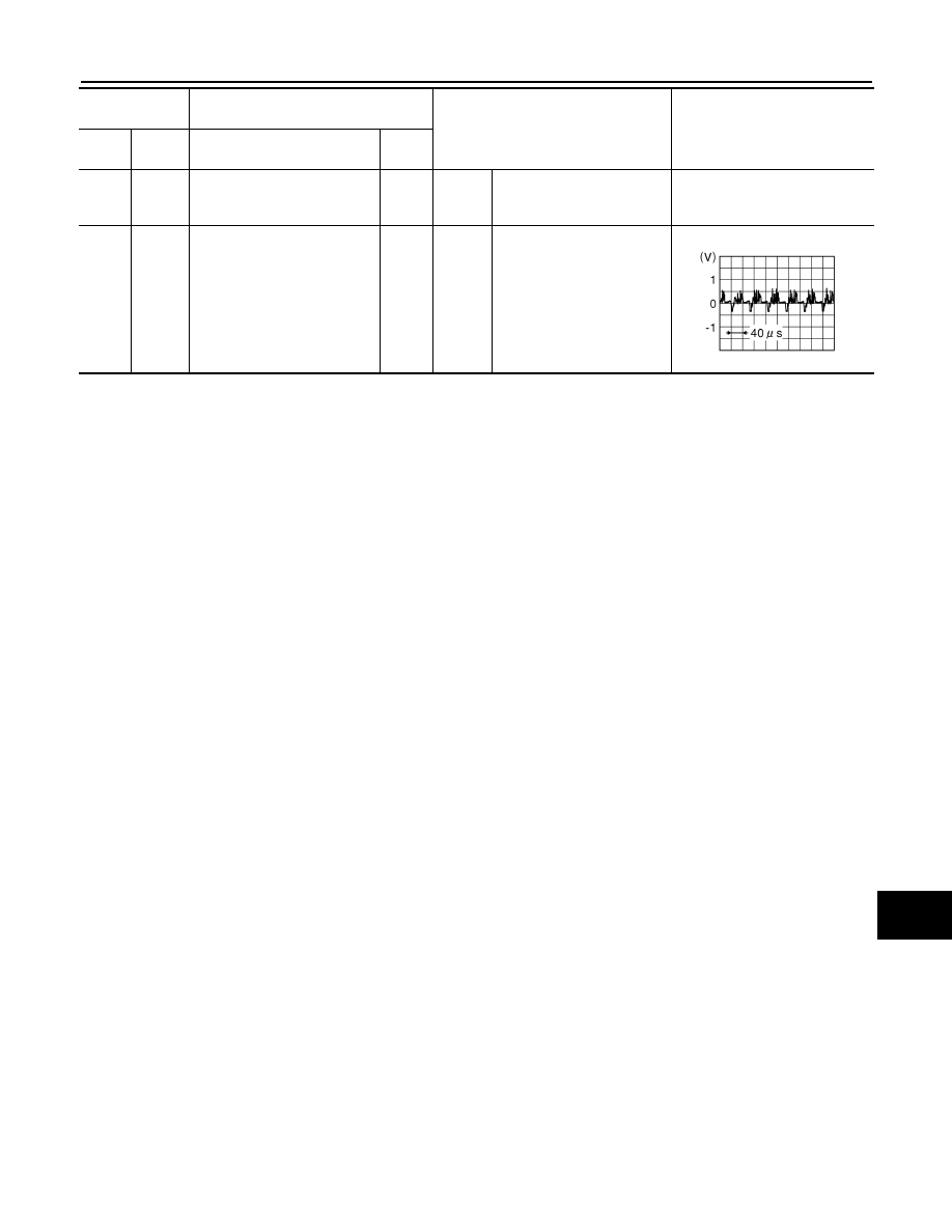
Side camera driver side image
signal
Input
Ignition
switch
ON
“CAMERA” switch is ON or
shift position is “R”.
Terminal
(Wire color)
Description
Condition
Reference value
(Approx.)
+
–
Signal name
Input/
Output
JSNIA0834GB
AV-426
< ECU DIAGNOSIS INFORMATION >
[NAVIGATION (TWIN MONITOR)]
SONAR CONTROL UNIT (WITH AROUND VIEW MONITOR)
SONAR CONTROL UNIT (WITH AROUND VIEW MONITOR)
Reference Value
INFOID:0000000005474762
VALUES ON THE DIAGNOSIS TOOL
CONSULT-III MONITOR ITEM
Monitor Item
Condition
Value/Status
SONAR OPE
Ignition switch
ON
Around view monitor operating (sonar operating).
On
Around view monitor non-operating (sonar non-operat-
ing).
Off
BUZZER OUTPUT
Ignition switch
ON
Buzzer is output condition.
On
Buzzer is not output condition.
Off
CR SEN [FL]
Ignition switch
ON
When a sensor is abnormal.
ERROR
When a sensor is not detection.
LV.0
The distance between the corner sensor and an obstacle
is 60 cm (23.6 in) or more and less then 70 cm (27.5 in).
LV.2
The distance between the corner sensor and an obstacle
is 40 cm (15.7 in) or more and less then 60 cm (23.6 in).
LV.3
The distance between corner sensor and an obstacle
less than 40 cm (15.7 in).
LV.4
CR SEN [FR]
Ignition switch
ON
When a sensor is abnormal.
ERROR
When a sensor is not detection.
LV.0
The distance between the corner sensor and an obstacle
is 60 cm (23.6 in) or more and less then 70 cm (27.5 in).
LV.2
The distance between the corner sensor and an obstacle
is 40 cm (15.7 in) or more and less then 60 cm (23.6 in).
LV.3
The distance between corner sensor and an obstacle
less than 40 cm (15.7 in).
LV.4
CR SEN [RL]
Ignition switch
ON
When a sensor is abnormal.
ERROR
When a sensor is not detection.
LV.0
The distance between the corner sensor and an obstacle
is 60 cm (23.6 in) or more and less then 70 cm (27.5 in).
LV.2
The distance between the corner sensor and an obstacle
is 40 cm (15.7 in) or more and less then 60 cm (23.6 in).
LV.3
The distance between corner sensor and an obstacle
less than 40 cm (15.7 in).
LV.4
CR SEN [RR]
Ignition switch
ON
When a sensor is abnormal.
ERROR
When a sensor is not detection.
LV.0
The distance between the corner sensor and an obstacle
is 60 cm (23.6 in) or more and less then 70 cm (27.5 in).
LV.2
The distance between the corner sensor and an obstacle
is 40 cm (15.7 in) or more and less then 60 cm (23.6 in).
LV.3
The distance between corner sensor and an obstacle
less than 40 cm (15.7 in).
LV.4
AV
SONAR CONTROL UNIT (WITH AROUND VIEW MONITOR)
AV-427
< ECU DIAGNOSIS INFORMATION >
[NAVIGATION (TWIN MONITOR)]
C
D
E
F
G
H
I
J
K
L
M
B
A
O
P
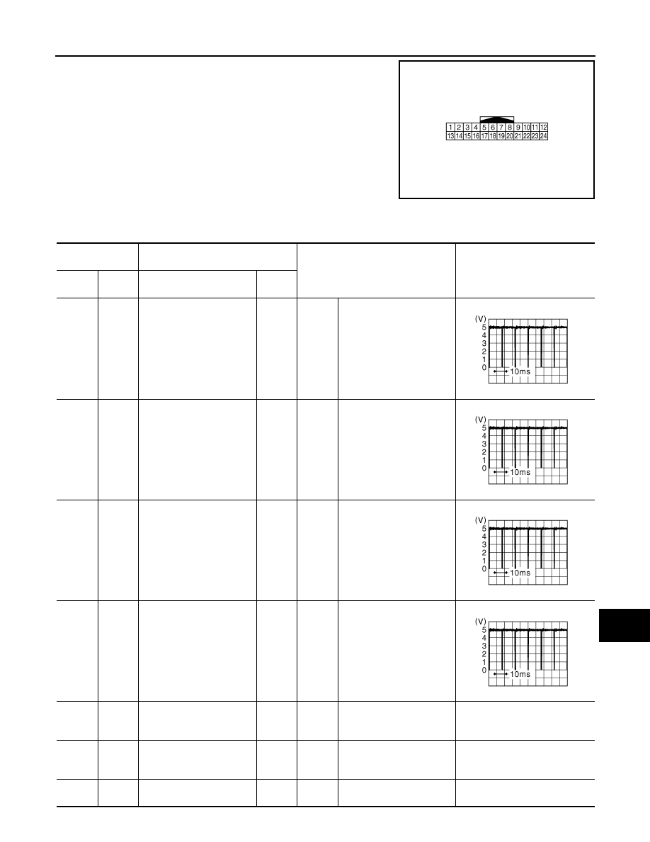
TERMINAL LAYOUT
PHYSICAL VALUES
JSNIA0303ZZ
Terminal No.
(Wire color)
Description
Condition
Value
(Approx.)
+
–
Signal name
Input/
Output
3
(W)
12
(B)
Corner sensor signal front
LH
Input
Ignition
switch
ON
“CAMERA” switch is ON or
shift position is “R”.
4
(R)
12
(B)
Corner sensor signal front
RH
Input
Ignition
switch
ON
“CAMERA” switch is ON or
shift position is “R”.
5
(W)
12
(B)
Corner sensor signal rear
LH
Input
Ignition
switch
ON
“CAMERA” switch is ON or
shift position is “R”.
6
(R)
12
(B)
Corner sensor signal rear
RH
Input
Ignition
switch
ON
“CAMERA” switch is ON or
shift position is “R”.
12
(B)
Ground
Sensor ground
—
Ignition
switch
ON
—
0 V
13
(V)
Ground
ACC power supply
Input
Ignition
switch
ACC
—
12.0 V
18
(P)
—
K-line (CONSULT-III)
—
—
—
—
JSNIA0837GB
JSNIA0837GB
JSNIA0837GB
JSNIA0837GB
AV-428
< ECU DIAGNOSIS INFORMATION >
[NAVIGATION (TWIN MONITOR)]
SONAR CONTROL UNIT (WITH AROUND VIEW MONITOR)
Fail-Safe
INFOID:0000000005474765
• Sonar control unit has diagnosis function which can detect corner sensor malfunction and sensor harness
disconnection.
• It transmits the malfunction status to around view monitor control unit and informs the malfunction to the user
by displaying continuously red sonar indicator.
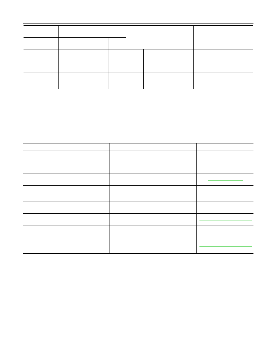
DTC Index
INFOID:0000000005474766
NOTE:
“TIME” means the following.
• 0: Means detected malfunction at present. (From malfunction detection to turning ignition switch OFF)
• 1–39: Means detected malfunction in past.
19
(G)
—
AV communication (H)
Input/
Output
—
—
—
20
(R)
—
AV communication (L)
Input/
Output
—
—
—
24
(B)
Ground
Ground
—
Ignition
switch
ON
—
0 V
Terminal No.
(Wire color)
Description
Condition
Value
(Approx.)
+
–
Signal name
Input/
Output
DTC
Display item
Malfunction is detected when...
Reference
B2700
CORNER SENSOR [FL]
[B2700]
Corner sensor (FL) is malfunctioning.
B2701
SENSOR HARNESS OPEN [CR-FL]
[B2701]
Corner sensor (FL) harness circuit is open.
B2702
CORNER SENSOR [FR]
[B2702]
Corner sensor (FR) is malfunctioning.
B2703
SENSOR HARNESS OPEN [CR-
FR]
[B2703]
Corner sensor (FR) harness circuit is open.
B2704
CORNER SENSOR [RL]
[B2704]
Corner sensor (RL) is malfunctioning.
B2705
SENSOR HARNESS OPEN [CR-RL]
[B2705]
Corner sensor (RL) harness circuit is open.
B2706
CORNER SENSOR [RR]
[B2706]
Corner sensor (RR) is malfunctioning.
B2707
SENSOR HARNESS OPEN [CR-
RR]
[B2707]
Corner sensor (RR) harness circuit is open.
Нет комментариевНе стесняйтесь поделиться с нами вашим ценным мнением.
Текст