Infiniti FX35, FX50 (S51). Manual — part 267
PARKING BRAKE SWITCH
BRC-99
< DTC/CIRCUIT DIAGNOSIS >
[VDC/TCS/ABS]
C
D
E
G
H
I
J
K
L
M
A
B
BRC
N
O
P
PARKING BRAKE SWITCH
Component Function Check
INFOID:0000000005234621
1.
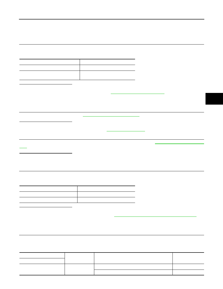
CHECK PARKING BRAKE SWITCH OPERATION
Operate the parking brake pedal. Then check that the brake warning lamp in the combination meter turns ON/
OFF correctly.
Is the inspection result normal?
YES
>> INSPECTION END
NO
>> Proceed to diagnosis procedure. Refer to
.
Diagnosis Procedure
INFOID:0000000005234622
1.
CHECK PARKING BRAKE SWITCH
Check parking brake switch. Refer to
BRC-99, "Component Inspection"
Is the inspection result normal?
YES
>> GO TO 2.
NO
>> Replace parking brake switch. Refer to
.
2.
CHECK COMBINATION METER
Check if the indication and operation of combination meter are normal. Refer to
.
Is the inspection result normal?
YES
>> GO TO 3.
NO
>> Repair or replace combination meter.
3.
CHECK DATA MONITOR
Select “ABS”, “DATA MONITOR” and “PARK BRAKE SW” in order with CONSULT-III, and perform the parking
brake switch inspection.
Is the inspection result normal?
YES
>> INSPECTION END
NO
>> Check unified meter and A/C amp. Refer to
MWI-45, "CONSULT-III Function (METER/M&A)"
Component Inspection
INFOID:0000000005234623
1.
CHECK PARKING BRAKE SWITCH
1.
Turn the ignition switch OFF.
2.
Disconnect parking brake switch harness connector.
3.
Check the continuity between parking brake switch harness connector and ground.
Condition
Brake warning lamp illumination status
When the parking brake pedal is operation
ON
When the parking brake pedal is not oper-
ation.
OFF
Condition
PARK BRAKE SW (DATA MONITOR)
Parking brake switch is active
ON
Parking brake switch is inactive
OFF
Parking brake switch
—
Condition
Continuity
Terminal
1
Ground
When the parking brake switch is operated.
Existed
When the parking brake switch is not operated.
Not existed
BRC-100
< DTC/CIRCUIT DIAGNOSIS >
[VDC/TCS/ABS]
PARKING BRAKE SWITCH
Is the inspection result normal?
YES
>> INSPECTION END
NO
>> Replace parking brake switch. Refer to
.
VDC OFF SWITCH
BRC-101
< DTC/CIRCUIT DIAGNOSIS >
[VDC/TCS/ABS]
C
D
E
G
H
I
J
K
L
M
A
B
BRC
N
O
P
VDC OFF SWITCH
Description
INFOID:0000000005234624
VDC OFF switch can deactivate (turn OFF) the VDC/TCS function by pressing the VDC OFF switch.
Component Function Check
INFOID:0000000005234625
1.
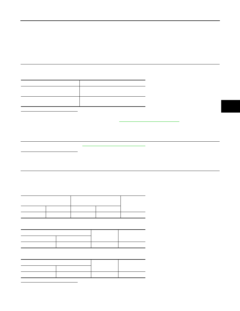
CHECK VDC OFF SWITCH OPERATION
Turn ON/OFF the VDC OFF switch and check that the VDC OFF indicator lamp in the combination meter turns
ON/OFF correctly.
Is the inspection result normal?
YES
>> INSPECTION END
NO
>> Proceed to diagnosis procedure. Refer to
BRC-101, "Diagnosis Procedure"
Diagnosis Procedure
INFOID:0000000005234626
1.
CHECK VDC OFF SWITCH
Check VDC OFF switch. Refer to
BRC-102, "Component Inspection"
.
Is the inspection result normal?
YES
>> GO TO 2.
NO
>> VDC OFF switch is malfunctioning. Replace VDC OFF switch.
2.
CHECK VDC OFF SWITCH HARNESS
1.
Disconnect ABS actuator and electric unit (control unit) harness connector.
2.
Disconnect VDC OFF switch harness connector.
3.
Check the continuity between VDC OFF switch harness connector and ABS actuator and electric unit
(control unit) connector.
4.
Check the continuity between ABS actuator and electric unit (control unit) harness connector and ground.
5.
Check the continuity between VDC OFF switch harness connector and ground.
Is the inspection result normal?
YES
>> GO TO 3.
NO
>> If the open or short in harness, repair or replace harness.
Condition
VDC OFF indicator lamp illumination status
Press the VDC OFF switch when VDC
OFF indicator lamp is OFF.
ON
Press the VDC OFF switch when VDC
OFF indicator lamp is ON.
OFF
ABS actuator and electric unit
(control unit)
VDC OFF switch
Continuity
Connector
Terminal
Connector
Terminal
E41
31
M19
1
Existed
ABS actuator and electric unit (control unit)
—
Continuity
Connector
Terminal
E41
31
Ground
Not existed
VDC OFF switch
—
Continuity
Connector
Terminal
M19
2
Ground
Existed
BRC-102
< DTC/CIRCUIT DIAGNOSIS >
[VDC/TCS/ABS]
VDC OFF SWITCH
3.
CHECK COMBINATION METER
1.
Connect ABS actuator and electric unit (control unit) harness connector.
2.
Connect VDC OFF switch harness connector.
3.
Check the indication and operation of combination meter are normal. Refer to
.
Is the inspection result normal?
YES
>> INSPECTION END
NO
>> Repair or replace combination meter.
Component Inspection
INFOID:0000000005234627
1.
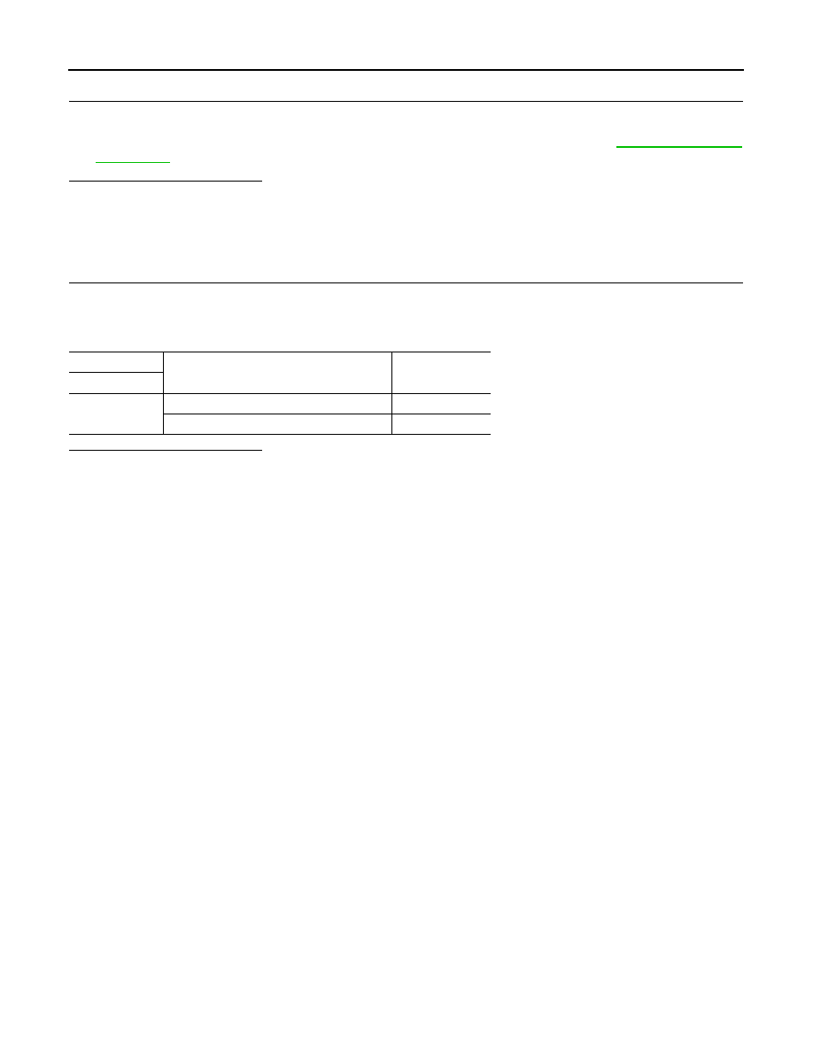
CHECK VDC OFF SWITCH
1.
Turn the ignition switch OFF.
2.
Disconnect VDC OFF switch harness connector.
3.
Check the continuity between VDC OFF switch harness connector terminals.
Is the inspection result normal?
YES
>> INSPECTION END
NO
>> Replace VDC OFF switch.
VDC OFF switch
Condition
Continuity
Terminal
1
−
2
When VDC OFF switch is hold pressed.
Existed
When releasing VDC OFF switch.
Not existed
Нет комментариевНе стесняйтесь поделиться с нами вашим ценным мнением.
Текст