Infiniti FX35, FX50 (S51). Manual — part 1003
EXL-8
< SYSTEM DESCRIPTION >
[XENON TYPE]
HEADLAMP SYSTEM
SYSTEM DESCRIPTION
HEADLAMP SYSTEM
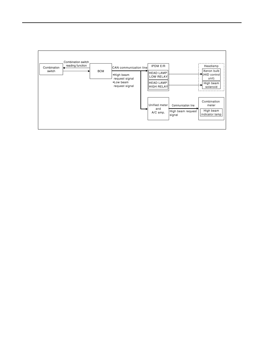
System Diagram
INFOID:0000000005244656
System Description
INFOID:0000000005244657
OUTLINE
• Mobile valve shade type is adopted. Xenon headlamp switches the high beam and the low beam with one
xenon bulb each on right and left.
• Headlamp is controlled by combination switch reading function and headlamp control function of BCM, and
relay control function of IPDM E/R.
HEADLAMP BASIC OPERATION
• BCM detects the combination switch condition with the combination switch reading function.
• BCM transmits the low beam request signal to IPDM E/R with CAN communication according to the head-
lamp ON condition.
Headlamp ON condition
- Lighting switch 2ND
- Lighting switch PASS
- Lighting switch AUTO, and the auto light function ON judgment
• IPDM E/R turns the integrated headlamp low relay ON, and turns the headlamp ON according to the low
beam request signal.
HEADLAMP HI/LO SWITCHING OPERATION
• BCM transmits the high beam request signal to IPDM E/R and the combination meter (through the unified
meter and A/C amp.) with CAN communication according to the high beam switching condition.
High beam switching condition
- Lighting switch HI with the headlamp ON
- Lighting switch PASS
• Combination meter turns the high beam indicator lamp ON according to the high beam request signal.
• IPDM E/R turns the integrated headlamp high relay ON, and turns the headlamp ON according to the high
beam request signal.
JPLIA0001GB
HEADLAMP SYSTEM
EXL-9
< SYSTEM DESCRIPTION >
[XENON TYPE]
C
D
E
F
G
H
I
J
K
M
A
B
EXL
N
O
P
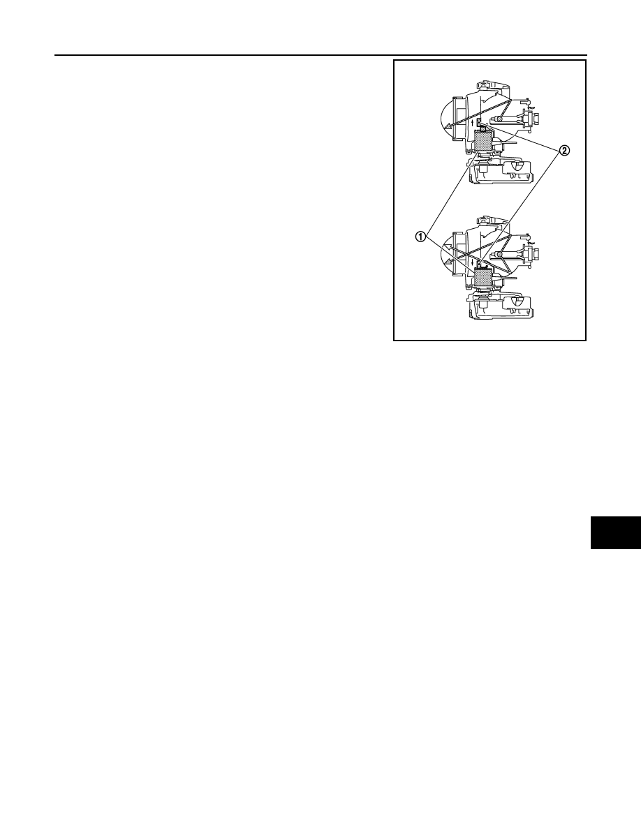
• When the headlamp high relay is turned ON, magnetic force is
applied to the high beam solenoid (1) by a current. The mobile
valve shade (2) is switched to the high beam position.
• When the headlamp high relay is turned OFF, the current stops.
The mobile valve shade returns to the low beam position automati-
cally.
JPLIA1158ZZ
EXL-10
< SYSTEM DESCRIPTION >
[XENON TYPE]
HEADLAMP SYSTEM
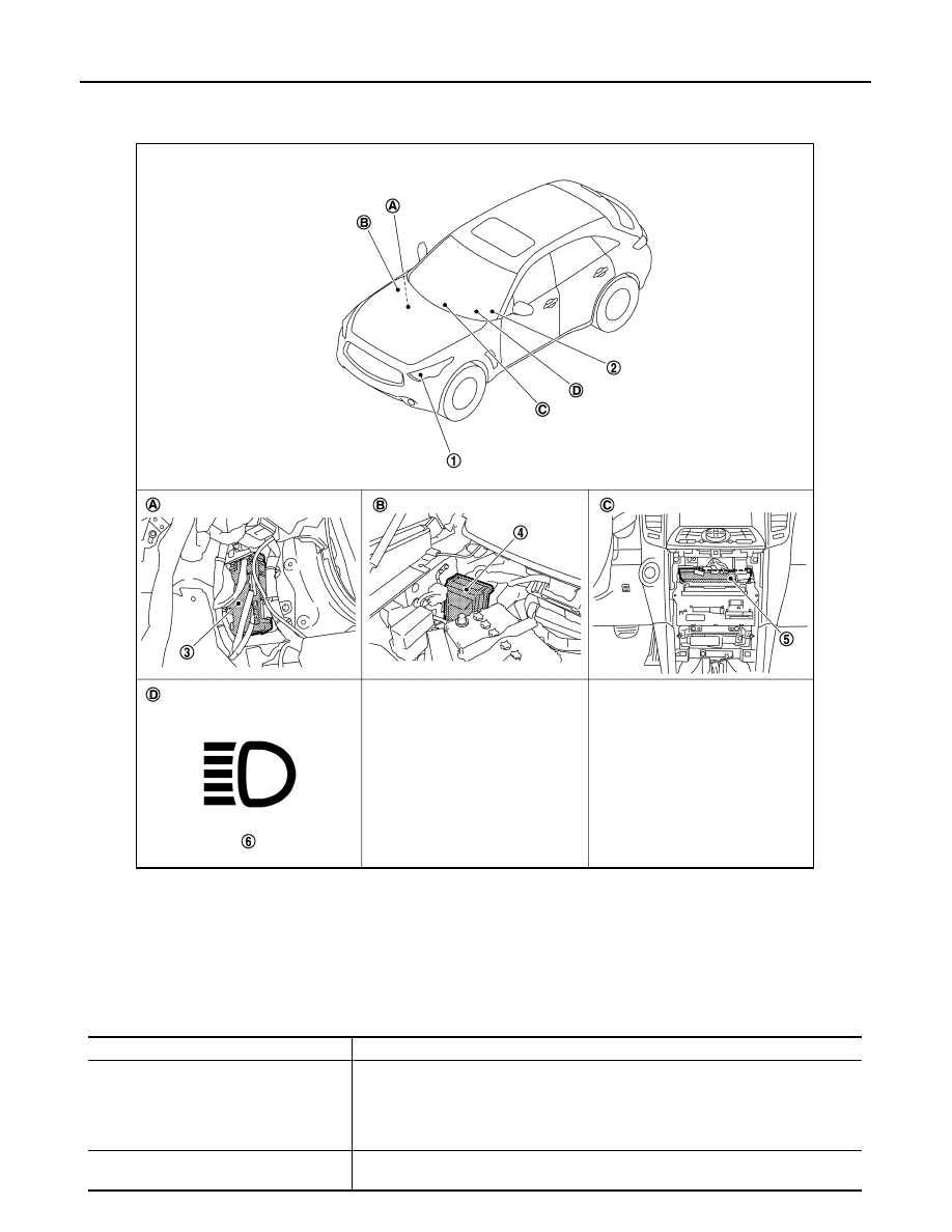
Component Parts Location
INFOID:0000000005244658
Component Description
INFOID:0000000005244659
1.
Headlamp
2.
Combination switch
3.
BCM
4.
IPDM E/R
5.
Unified meter and A/C amp.
6.
High beam indicator lamp
A.
Dash side lower (passenger side)
B.
Engine room dash panel (RH)
C.
Behind cluster lid C
D.
On the combination meter
JPMIA1091ZZ
Part
Description
BCM
• Detects each switch condition by the combination switch reading function.
• Judges that the headlamp is turned ON according to the vehicle condition.
- Requests the headlamp relay (HI/LO) ON to IPDM E/R (with CAN communication).
- Requests the high beam indicator lamp ON to the combination meter [with CAN
communication (through the unified meter and A/C amp.)].
IPDM E/R
Controls the integrated relay, and supplies voltage to the load according to the request
from BCM (with CAN communication).
HEADLAMP SYSTEM
EXL-11
< SYSTEM DESCRIPTION >
[XENON TYPE]
C
D
E
F
G
H
I
J
K
M
A
B
EXL
N
O
P
Combination switch
(Lighting & turn signal switch)
Refer to
.
Combination meter
(High beam indicator lamp)
Turns the high beam indicator lamp ON according to the request from BCM [with CAN
communication (through the unified meter and A/C amp.)].
Headlamp assem-
bly
• HID control unit
• Xenon bulb
Refer to
High beam solenoid
Refer to
Part
Description
Нет комментариевНе стесняйтесь поделиться с нами вашим ценным мнением.
Текст