Infiniti FX35, FX50 (S51). Manual — part 189
AV
MICROPHONE SIGNAL CIRCUIT
AV-529
< DTC/CIRCUIT DIAGNOSIS >
[NAVIGATION (TWIN MONITOR)]
C
D
E
F
G
H
I
J
K
L
M
B
A
O
P
Is the inspection result normal?
YES
>> Replace AV control unit. Refer to
NO
>> Replace microphone. Refer to
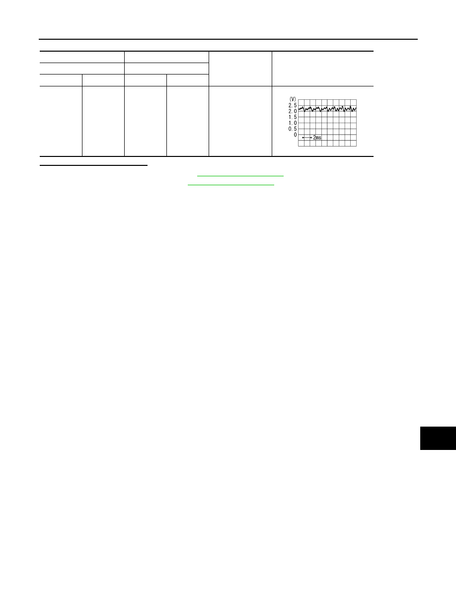
(+)
(
−
)
Condition
Reference value
AV control unit
AV control unit
Connector
Terminal
Connector
Terminal
M210
87
M210
71
Give a voice.
PKIB5037J
AV-530
< DTC/CIRCUIT DIAGNOSIS >
[NAVIGATION (TWIN MONITOR)]
CAMERA IMAGE SIGNAL CIRCUIT (AROUND VIEW MONITOR CONTROL UNIT
TO DISPLAY UNIT)
CAMERA IMAGE SIGNAL CIRCUIT (AROUND VIEW MONITOR CONTROL
UNIT TO DISPLAY UNIT)
Description
INFOID:0000000005474885
Around view monitor control unit supplies to the front camera, rear camera and side camera. And then it
superimpose the images from each camera and outputs then to the front display unit.
Diagnosis Procedure
INFOID:0000000005474886
1.
CHECK CONTINUITY CAMERA IMAGE SIGNAL CIRCUIT
1.
Turn ignition switch OFF.
2.
Disconnect front display unit connector and around view monitor control unit connector.
3.
Check continuity between front display unit harness connector and around view monitor control unit har-
ness connector.
4.
Check continuity between front display unit harness connector and ground.
Is inspection result normal?
YES
>> GO TO 2.
NO
>> Repair harness or connector.
2.
CHECK CAMERA IMAGE SIGNAL
1.
Connect front display unit connector and around view monitor control unit connector.
2.
Turn ignition switch ON.
3.
Check signal between front display unit harness connector and ground.
Is inspection result normal?
YES
>> Replace front display unit. Refer to
.
NO
>> Replace around view monitor control unit. Refer to
.
Front display unit
Around view monitor control
unit
Continuity
Connector
Terminal
Connector
Terminal
M195
8
B46
27
Existed
Front display unit
Ground
Continuity
Connector
Terminal
M195
8
Not existed
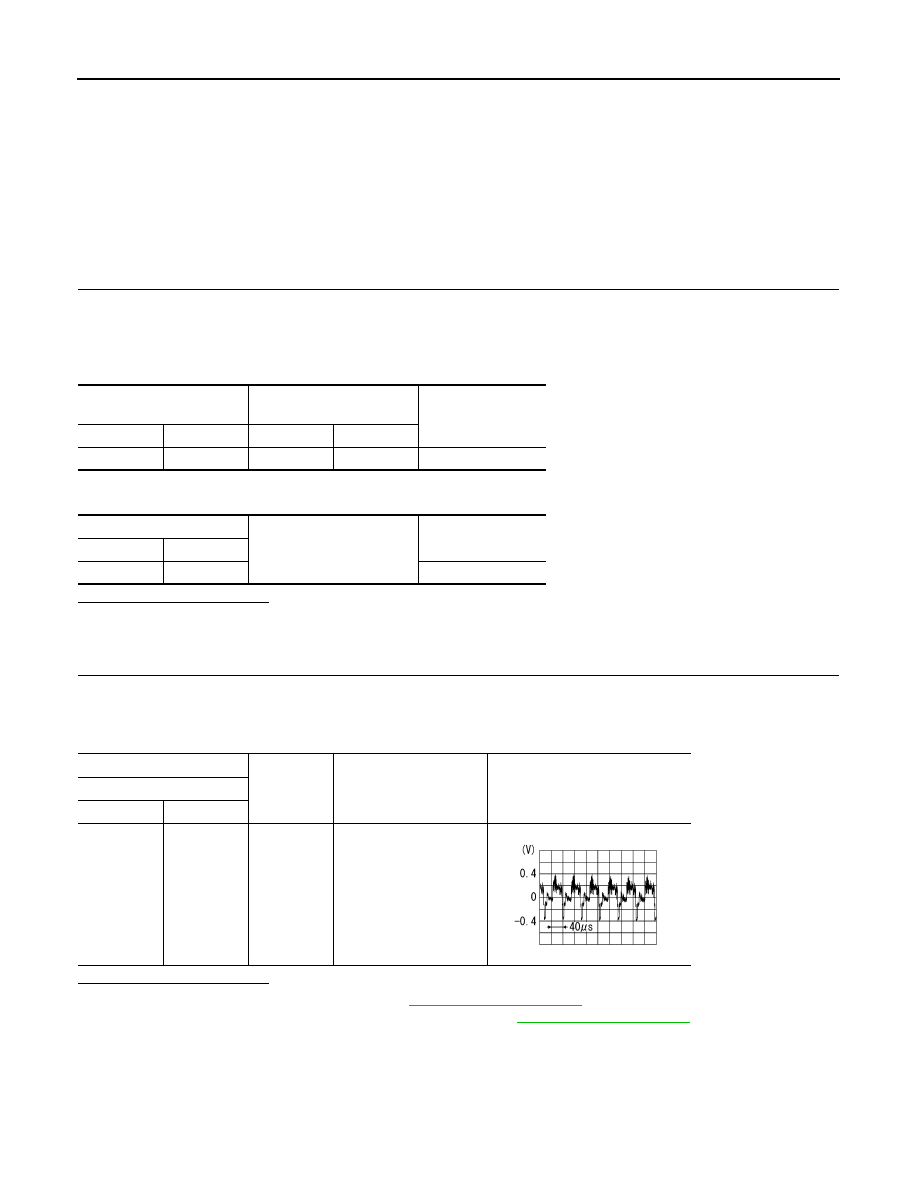
(+)
(
−
)
Condition
Reference value
Front display unit
Connector
Terminal
M195
8
Ground
At camera image is dis-
played.
SKIB2251J
AV
FRONT CAMERA COMMUNICATION SIGNAL CIRCUIT
AV-531
< DTC/CIRCUIT DIAGNOSIS >
[NAVIGATION (TWIN MONITOR)]
C
D
E
F
G
H
I
J
K
L
M
B
A
O
P
FRONT CAMERA COMMUNICATION SIGNAL CIRCUIT
Description
INFOID:0000000005474887
• Around view monitor control unit supplies to the front camera, rear camera and side camera. And then it
superimpose the images from each camera and outputs then to the display unit.
• Superimpose the guiding lines, predicted course line and sonar indicator to the camera image that outputs to
the front display unit.
• Around view monitor control unit performs the reception/transmission of communication signal with each
camera.
Diagnosis Procedure
INFOID:0000000005474888
1.
CHECK CONTINUITY COMMUNICATION SIGNAL CIRCUIT
1.
Turn ignition switch OFF.
2.
Disconnect around view monitor control unit connector and front camera connector.
3.
Check continuity between around view monitor control unit harness connector and front camera harness
connector.
4.
Check continuity between around view monitor control unit harness connector and ground.
Is inspection result normal?
YES
>> GO TO 2.
NO
>> Repair harness or connector.
2.
CHECK COMMUNICATION SIGNAL
1.
Connect around view monitor control unit connector and front camera connector.
2.
Turn ignition switch ON.
3.
Check signal between around view monitor control unit harness connector and ground.
Is inspection result normal?
YES
>> Replace around view monitor control unit. Refer to
.
NO
>> Replace front camera. Refer to
.
Around view monitor control
unit
Front camera
Continuity
Connector
Terminal
Connector
Terminal
B45
45
E155
6
Existed
Around view monitor control
unit
Ground
Continuity
Connector
Terminal
B45
45
Not existed
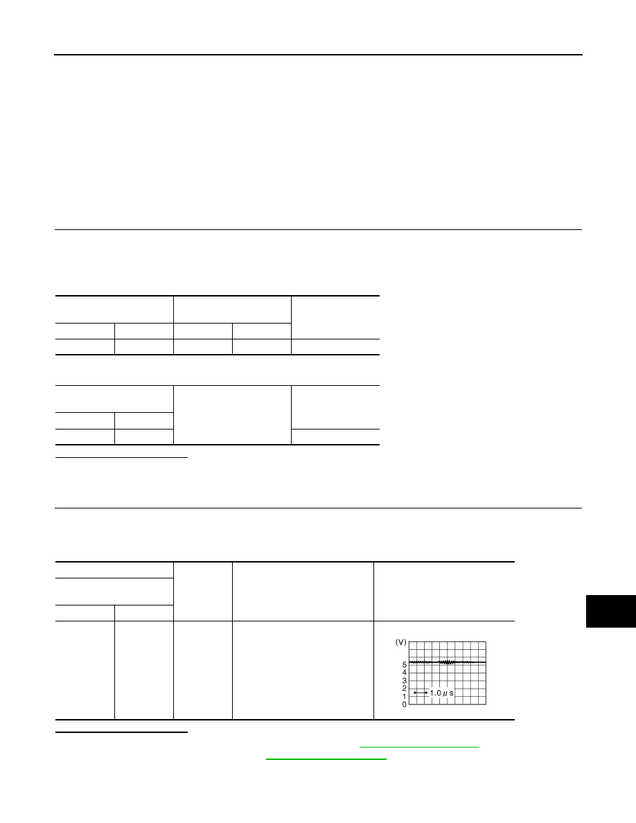
(+)
(
−
)
Condition
Reference value
Around view monitor control
unit
Connector
Terminal
B45
45
Ground
“CAMERA” switch is ON or shift
position is “R”.
JSNIA0836GB
AV-532
< DTC/CIRCUIT DIAGNOSIS >
[NAVIGATION (TWIN MONITOR)]
FRONT CAMERA IMAGE SIGNAL CIRCUIT
FRONT CAMERA IMAGE SIGNAL CIRCUIT
Description
INFOID:0000000005525406
• Around view monitor control unit supplies to the front camera, rear camera and side camera. And then it
superimpose the images from each camera and outputs then to the display unit.
• Superimpose the guiding lines, predicted course line and sonar indicator to the camera image that outputs to
the front display unit.
• Around view monitor control unit performs the reception/transmission of communication signal with each
camera.
Diagnosis Procedure
INFOID:0000000005474890
1.
CHECK CONTINUITY FRONT CAMERA POWER SUPPLY AND GROUND CIRCUIT
1.
Turn ignition switch OFF.
2.
Disconnect around view monitor control unit connector and front camera connector.
3.
Check continuity between around view monitor control unit harness connector and front camera harness
connector.
4.
Check continuity between around view monitor control unit harness connector and ground.
Is inspection result normal?
YES
>> GO TO 2.
NO
>> Repair harness or connector.
2.
CHECK VOLTAGE FRONT CAMERA POWER SUPPLY
1.
Connect around view monitor control unit connector and front camera connector.
2.
Turn ignition switch ON.
3.
Check voltage between around view monitor control unit harness connector.
Is inspection result normal?
YES
>> GO TO 3.
NO
>> Replace around view monitor control unit. Refer to
.
3.
CHECK CONTINUITY FRONT CAMERA IMAGE SIGNAL CIRCUIT
1.
Turn ignition switch OFF.
2.
Disconnect around view monitor control unit connector and front camera connector.
3.
Check continuity between around view monitor control unit harness connector and front camera harness
connector.
Around view monitor control
unit
Front camera
Continuity
Connector
Terminals
Connector
Terminals
B45
44
E155
2
Existed
46
1
Around view monitor control
unit
Ground
Continuity
Connector
Terminal
B45
46
Not existed
(+)
(
−
)
Condition
Voltage
(Approx.)
Around view monitor control
unit
Connector
Terminal
B45
46
Ground
“CAMERA” switch is ON or
shift position is “R”.
6.0 V
Нет комментариевНе стесняйтесь поделиться с нами вашим ценным мнением.
Текст