Infiniti FX35, FX50 (S51). Manual — part 187
AV
COMPOSITE IMAGE SIGNAL CIRCUIT (VIDEO DISTRIBUTOR TO REAR DIS-
PLAY UNIT)
AV-521
< DTC/CIRCUIT DIAGNOSIS >
[NAVIGATION (TWIN MONITOR)]
C
D
E
F
G
H
I
J
K
L
M
B
A
O
P
COMPOSITE IMAGE SIGNAL CIRCUIT (VIDEO DISTRIBUTOR TO REAR
DISPLAY UNIT)
Description
INFOID:0000000005550410
• DVD is played by inserting DVD into the AV control unit.
• DVD image signals are transmitted to the front display unit and video distributor.
• AV control unit receives the image signal from the auxiliary input jacks and USB (video data) and then trans-
mits it to the video distributor.
• Video distributor receives the image signal from the AV control unit and then transmits it to the rear display
unit.
Diagnosis Procedure
INFOID:0000000005247327
1.
CHECK CONTINUITY COMPOSITE IMAGE SIGNAL CIRCUIT
1.
Turn ignition switch OFF.
2.
Disconnect video distributor connector and rear display unit connector.
3.
Check continuity between video distributor harness connector and rear display unit harness connector.
4.
Check continuity between rear display unit harness connector and ground.
Is the inspection result normal?
YES
>> GO TO 2.
NO
>> Repair harness or connector.
2.
CHECK COMPOSITE IMAGE SIGNAL
1.
Connect video distributor connector and rear display unit connector.
2.
Turn ignition switch ON.
3.
Check signal between rear display unit harness connector using an oscilloscope.
Is the inspection result normal?
YES
>> Replace rear display unit.
NO
>> Replace video distributor.
Video distributor
Rear display unit
Continuity
Connector
Terminal
Connector
Terminal
M97
34
B26
14
Existed
Rear display unit
Ground
Continuity
Connector
Terminal
B26
14
Not existed
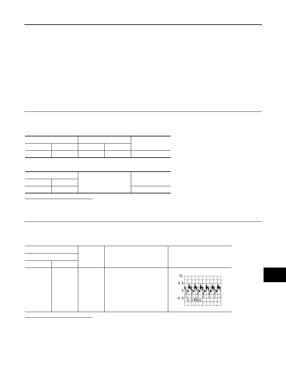
(+)
(
−
)
Condition
Reference value
Rear display unit
Connector
Terminal
B26
14
Ground
When AUX or DVD image is dis-
played on rear display unit.
SKIB2251J
AV-522
< DTC/CIRCUIT DIAGNOSIS >
[NAVIGATION (TWIN MONITOR)]
COMPOSITE IMAGE SIGNAL CIRCUIT (VIDEO DISTRIBUTOR TO AV CONTROL
UNIT)
COMPOSITE IMAGE SIGNAL CIRCUIT (VIDEO DISTRIBUTOR TO AV
CONTROL UNIT)
Description
INFOID:0000000005550434
• DVD is played by inserting DVD into the AV control unit.
• DVD image signals are transmitted to the front display unit and video distributor.
• AV control unit receives the image signal from the auxiliary input jacks and USB (video data) and then trans-
mits it to the video distributor.
• Video distributor receives the image signal from the AV control unit and then transmits it to the rear display
unit.
Diagnosis Procedure
INFOID:0000000005550411
1.
CHECK CONTINUITY COMPOSITE IMAGE SIGNAL CIRCUIT
1.
Turn ignition switch OFF.
2.
Disconnect video distributor connector and AV control unit connector.
3.
Check continuity between video distributor harness connector and AV control unit harness connector.
4.
Check continuity between rear display unit harness connector and ground.
Is the inspection result normal?
YES
>> GO TO 2.
NO
>> Repair harness or connector.
2.
CHECK COMPOSITE IMAGE SIGNAL
1.
Connect video distributor connector and AV control unit connector.
2.
Turn ignition switch ON.
3.
Check signal between video distributor harness connector using an oscilloscope.
Is the inspection result normal?
YES
>> Replace video distributor.
NO
>> Replace AV control unit.
Video distributor
AV control unit
Continuity
Connector
Terminal
Connector
Terminal
M98
23
M209
34
Existed
Video distributor
Ground
Continuity
Connector
Terminal
M98
23
Not existed
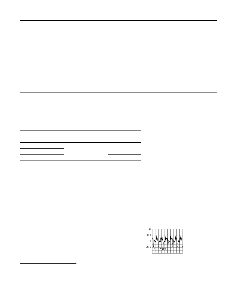
(+)
(
−
)
Condition
Reference value
Rear display unit
Connector
Terminal
M98
23
Ground
When AUX or DVD image is dis-
played on rear display unit.
SKIB2251J

AV
RGB DIGITAL IMAGE SIGNAL CIRCUIT
AV-523
< DTC/CIRCUIT DIAGNOSIS >
[NAVIGATION (TWIN MONITOR)]
C
D
E
F
G
H
I
J
K
L
M
B
A
O
P
RGB DIGITAL IMAGE SIGNAL CIRCUIT
Description
INFOID:0000000005474871
Transmit the image displayed with AV control unit with RGB digital image signal to the display unit.
Diagnosis Procedure
INFOID:0000000005474872
1.
CHECK CONTINUITY RGB DIGITAL IMAGE SIGNAL CIRCUIT
1.
Turn ignition switch OFF.
2.
Disconnect display unit connector and AV control unit connector.
3.
Check continuity between front display unit harness connector and AV control unit harness connector.
4.
Check continuity between front display unit harness connector and ground.
Is the inspection result normal?
YES
>> GO TO 2.
NO
>> Repair harness or connector.
2.
CHECK RGB DIGITAL IMAGE SIGNAL
1.
Connect AV control unit connector.
2.
Turn ignition switch ON.
3.
Check signal between front display unit harness connector and ground.
Is the inspection result normal?
YES
>> Replace front display unit. Refer to
.
NO
>> Replace AV control unit. Refer to
Front display unit
AV control unit
Continuity
Connector
Terminals
Connector
Terminals
M397
27
M396
157
Existed
28
158
Front display unit
Ground
Continuity
Connector
Terminals
M397
27
Not existed
28
(+)
(
−
)
Condition
Voltage
(Approx.)
Front display unit
Connector
Terminal
M397
27
Ground
—
3.0 V
28
AV-524
< DTC/CIRCUIT DIAGNOSIS >
[NAVIGATION (TWIN MONITOR)]
COMPOSITE IMAGE SIGNAL CIRCUIT (AV CONTROL UNIT TO FRONT DIS-
PLAY UNIT)
COMPOSITE IMAGE SIGNAL CIRCUIT (AV CONTROL UNIT TO FRONT
DISPLAY UNIT)
Description
INFOID:0000000005550435
• DVD is played by inserting DVD into the AV control unit.
• DVD image signals are transmitted to the front display unit and video distributor.
• AV control unit receives the image signal from the auxiliary input jacks and USB (video data) and then trans-
mits it to the video distributor.
• Video distributor receives the image signal from the AV control unit and then transmits it to the rear display
unit.
Diagnosis Procedure
INFOID:0000000005474874
1.
CHECK CONTINUITY COMPOSITE IMAGE SIGNAL CIRCUIT
1.
Turn ignition switch OFF.
2.
Disconnect AV control unit connector and front display unit connector.
3.
Check continuity between AV control unit harness connector and front display unit harness connector.
4.
Check continuity between AV control unit harness connector and ground.
Is the inspection result normal?
YES
>> GO TO 2.
NO
>> Repair harness or connector.
2.
CHECK AUX COMPOSITE SIGNAL
1.
Connect AV control unit connector and front display unit connector.
2.
Turn ignition switch ON.
3.
Check signal between auxiliary input jacks harness connector and ground.
Is the inspection result normal?
YES
>> Replace front display unit. Refer to
.
NO
>> Replace AV control unit. Refer to
AV control unit
Front display unit
Continuity
Connector
Terminal
Connector
Terminal
M210
68
M195
18
Existed
AV control unit
Ground
Continuity
Connector
Terminal
M210
68
Not existed
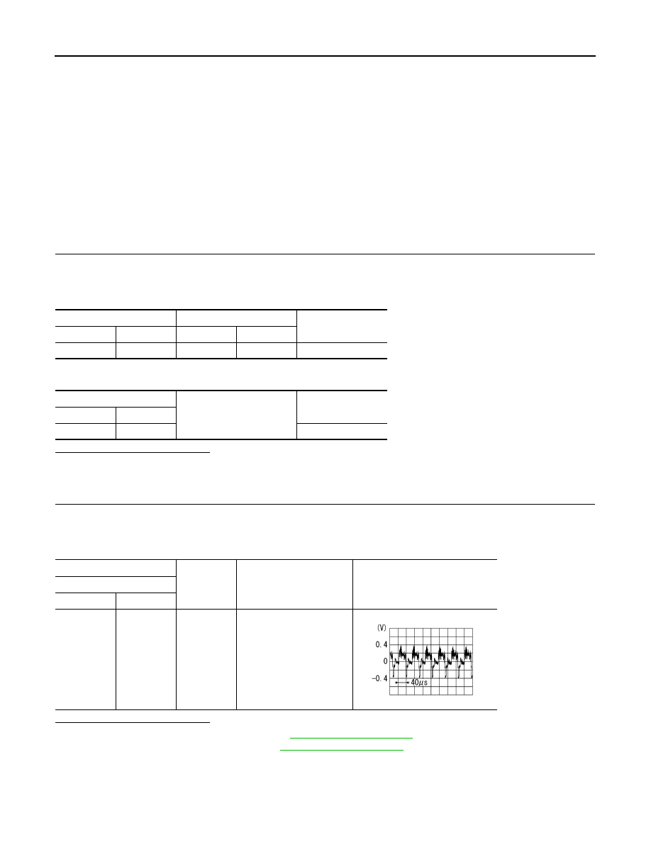
(+)
(
−
)
Condition
Reference value
AV control unit
Connector
Terminal
M210
68
Ground
At DVD image is displayed.
SKIB2251J
Нет комментариевНе стесняйтесь поделиться с нами вашим ценным мнением.
Текст