Infiniti FX35, FX50 (S51). Manual — part 653
P0014, P0024 EVT CONTROL
EC-153
< DTC/CIRCUIT DIAGNOSIS >
[VQ35HR]
C
D
E
F
G
H
I
J
K
L
M
A
EC
N
P
O
CAUTION:
Always drive vehicle at a safe speed.
3.
Check 1st trip DTC.
With GST
Follow the procedure “With CONSULT-III” above.
Is 1st trip DTC detected?
YES
>> Go to
NO
>> INSPECTION END
Diagnosis Procedure
INFOID:0000000005236751
1.
CHECK FUNCTION OF EXHAUST VALVE TIMING (EVT) CONTROL
With CONSULT-III
1.
Turn ignition switch ON.
2.
Select “EXH V/T ASSIGN ANGLE” in “ACTIVE TEST” mode with CONSULT-III.
3.
Start engine and keep the engine speed at 2,500 rpm, then touch “START”.
4.
Check that the values of “EXH/V TIM B1” and “EXH/V TIM B2” change when touching “UP” or “DOWN”.
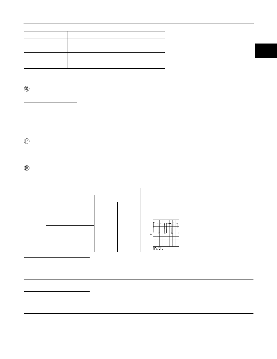
Without CONSULT-III
1.
Start engine and rev engine up above 1,500 rpm.
2.
Read the voltage signal between ECM harness connector terminals as follows with an oscilloscope.
Is the inspection result normal?
YES
>> GO TO 10.
NO
>> GO TO 2.
2.
CHECK EVT CONTROL MAGNET RETARDER
EC-154, "Component Inspection"
Is the inspection result normal?
YES
>> GO TO 4.
NO
>> GO TO 3.
3.
REPLACE EVT CONTROL MAGNET RETARDER
1.
Replace malfunctioning EVT control magnet retarder.
2.
EC-27, "EXHAUST VALVE TIMING CONTROL LEARNING : Special Repair Requirement"
>> INSPECTION END
ENG SPEED
1,400 - 2,950 rpm (A constant rotation is maintained.)
COOLAN TEMP/S
More than 70
°
C (158
°
F)
Selector lever
1st or 2nd position
Driving location uphill
Driving vehicle uphill
(Increased engine load will help maintain the driving
conditions required for this test.)
ECM
Voltage signal
+
–
Connector
Terminal
Connector
Terminal
F101
6
[EVT control magnet re-
tarder (bank 1) signal]
M107
128
7
[EVT control magnet re-
tarder (bank 2) signal]
JMBIA0034GB
EC-154
< DTC/CIRCUIT DIAGNOSIS >
[VQ35HR]
P0014, P0024 EVT CONTROL
4.
CHECK EVT CONTROL POSITION SENSOR
EC-369, "Component Inspection"
Is the inspection result normal?
YES
>> GO TO 5.
NO
>> Replace malfunctioning EVT control position sensor.
5.
CHECK CRANKSHAFT POSITION SENSOR
EC-271, "Component Inspection"
Is the inspection result normal?
YES
>> GO TO 6.
NO
>> Replace crankshaft position sensor.
6.
CHECK CAMSHAFT POSITION SENSOR
EC-277, "Component Inspection"
Is the inspection result normal?
YES
>> GO TO 7.
NO
>> Replace malfunctioning camshaft position sensor.
7.
CHECK CAMSHAFT (EXH)
Check the following.
• Accumulation of debris to the signal plate of camshaft rear end
• Chipping signal plate of camshaft rear end
Is the inspection result normal?
YES
>> GO TO 8.
NO
>> Remove debris and clean the signal plate of camshaft
rear end or replace camshaft.
8.
CHECK TIMING CHAIN INSTALLATION
Check service records for any recent repairs that may cause timing chain misaligned.
Are there any service records that may cause timing chain misaligned?
YES
>> Check timing chain installation. Refer to
EM-54, "Removal and Installation"
.
NO
>> GO TO 9.
9.
REPLACE EVT CONTROL PULLEY ASSEMBLY
1.
Replace exhaust valve timing control pulley assembly and EVT control magnet retarder.
Refer to
EM-54, "Removal and Installation"
EM-70, "Removal and Installation"
2.
EC-27, "EXHAUST VALVE TIMING CONTROL LEARNING : Special Repair Requirement"
>> INSPECTION END
10.
CHECK INTERMITTENT INCIDENT
GI-36, "Intermittent Incident"
>> INSPECTION END
Component Inspection
INFOID:0000000005236752
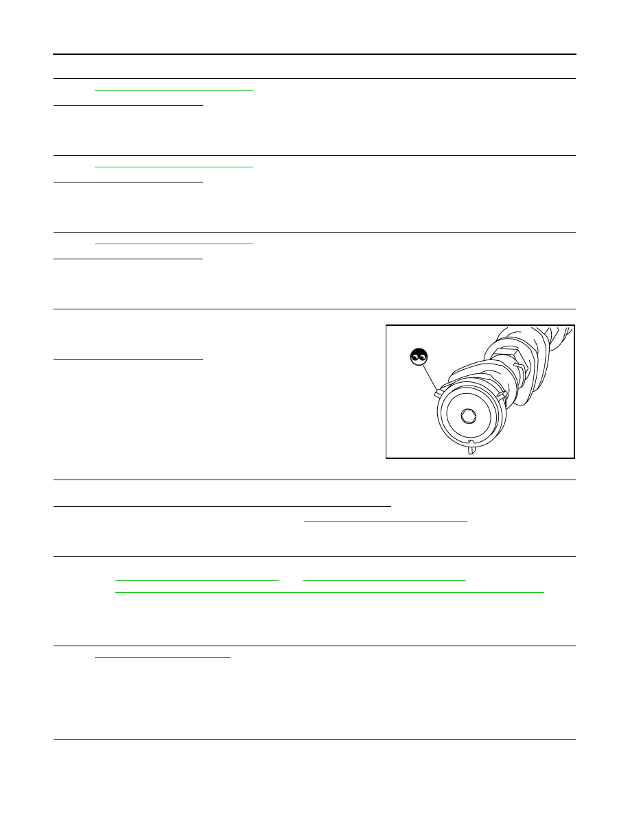
1.
CHECK EXHAUST VALVE TIMING CONTROL MAGNET RETARDER
1.
Turn ignition switch OFF.
2.
Disconnect exhaust valve timing control magnet retarder harness connector.
3.
Check resistance between exhaust valve timing control magnet retarder terminals as follows.
JMBIA0059ZZ

P0014, P0024 EVT CONTROL
EC-155
< DTC/CIRCUIT DIAGNOSIS >
[VQ35HR]
C
D
E
F
G
H
I
J
K
L
M
A
EC
N
P
O
Is the inspection result normal?
YES
>> INSPECTION END
NO
>> GO TO 2.
2.
REPLACE EXHAUST VALVE TIMING CONTROL MAGNET RETARDER
1.
Replace malfunctioning exhaust valve timing control magnet retarder.
2.
EC-27, "EXHAUST VALVE TIMING CONTROL LEARNING : Special Repair Requirement"
>> INSPECTION END
Terminals
Resistance
1 and 2
9.0 - 11.0
Ω
[at 20
°
C (68
°
F)]

EC-156
< DTC/CIRCUIT DIAGNOSIS >
[VQ35HR]
P0031, P0032, P0051, P0052 A/F SENSOR 1 HEATER
P0031, P0032, P0051, P0052 A/F SENSOR 1 HEATER
Description
INFOID:0000000005236753
SYSTEM DESCRIPTION
The ECM performs ON/OFF duty control of the A/F sensor 1 heater corresponding to the engine operating
condition to keep the temperature of A/F sensor 1 element within the specified range.
DTC Logic
INFOID:0000000005236754
DTC DETECTION LOGIC
DTC CONFIRMATION PROCEDURE
1.
PRECONDITIONING
If DTC Confirmation Procedure has been previously conducted, always perform the following procedure
before conducting the next test.
1.
Turn ignition switch OFF and wait at least 10 seconds.
2.
Turn ignition switch ON.
3.
Turn ignition switch OFF and wait at least 10 seconds.
TESTING CONDITION:
Before performing the following procedure, confirm that battery voltage is between 10.5 V and 16 V at
idle.
>> GO TO 2.
2.
PERFORM DTC CONFIRMATION PROCEDURE
1.
Start engine and let it idle for at least 10 seconds.
2.
Check 1st trip DTC.
Is 1st trip DTC detected?
YES
>> Go to
NG
>> INSPECTION END
Sensor
Input signal to ECM
ECM function
Actuator
Camshaft position sensor
Crankshaft position sensor
Engine speed
Air fuel ratio (A/F) sensor 1
heater control
Air fuel ratio (A/F) sensor 1
heater
Mass air flow sensor
Amount of intake air
DTC No.
Trouble diagnosis name
DTC detecting condition
Possible cause
P0031
Air fuel ratio (A/F) sensor
1 heater (bank 1) control
circuit low
The current amperage in the A/F sensor 1 heater
circuit is out of the normal range.
(An excessively low voltage signal is sent to ECM
through the A/F sensor 1 heater.)
• Harness or connectors
(The A/F sensor 1 heater circuit is
open or shorted.)
• A/F sensor 1 heater
P0032
Air fuel ratio (A/F) sensor
1 heater (bank 1) control
circuit high
The current amperage in the A/F sensor 1 heater
circuit is out of the normal range.
(An excessively high voltage signal is sent to ECM
through the A/F sensor 1 heater.)
• Harness or connectors
(The A/F sensor 1 heater circuit is
shorted.)
• A/F sensor 1 heater
P0051
Air fuel ratio (A/F) sensor
1 heater (bank 2) control
circuit low
The current amperage in the A/F sensor 1 heater
circuit is out of the normal range.
(An excessively low voltage signal is sent to ECM
through the A/F sensor 1 heater.)
• Harness or connectors
(The A/F sensor 1 heater circuit is
open or shorted.)
• A/F sensor 1 heater
P0052
Air fuel ratio (A/F) sensor
1 heater (bank 2) control
circuit high
The current amperage in the A/F sensor 1 heater
circuit is out of the normal range.
(An excessively high voltage signal is sent to ECM
through the A/F sensor 1 heater.)
• Harness or connectors
(The A/F sensor 1 heater circuit is
shorted.)
• A/F sensor 1 heater
Нет комментариевНе стесняйтесь поделиться с нами вашим ценным мнением.
Текст