Infiniti FX35, FX50 (S51). Manual — part 1137
REFRIGERATION SYSTEM
HA-61
< SYSTEM DESCRIPTION >
[VK50VE]
C
D
E
F
G
H
J
K
L
M
A
B
HA
N
O
P
SYSTEM DESCRIPTION
REFRIGERATION SYSTEM
System Diagram
INFOID:0000000005249933
System Description
INFOID:0000000005249934
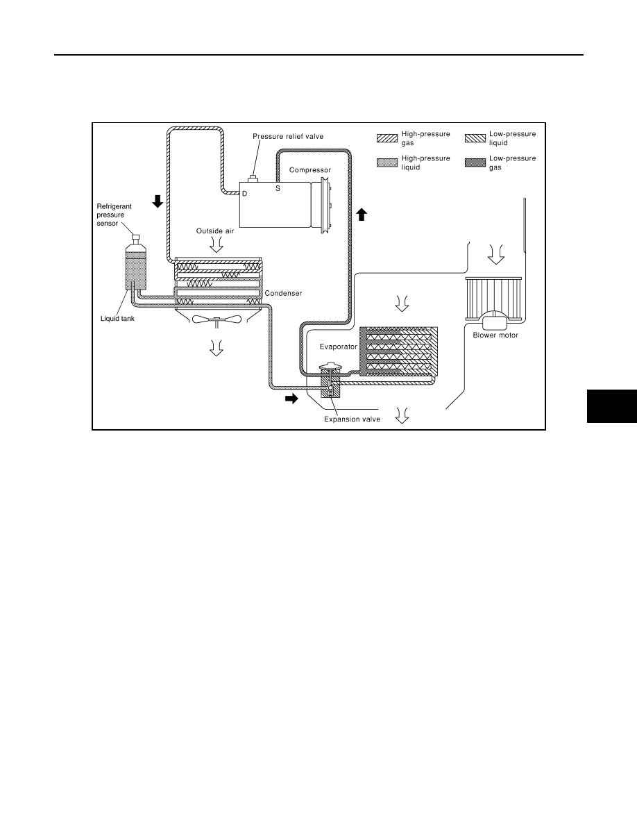
REFRIGERANT CYCLE
Refrigerant Flow
The refrigerant flows from the compressor, through the condenser with liquid tank, through the evaporator, and
back to the compressor. The refrigerant evaporation in the evaporator is controlled by an externally equalized
expansion valve, located inside the evaporator case.
Freeze Protection
To prevent evaporator from freezing up, the evaporator air temperature is monitored, and the voltage signal to
the unified meter and A/C amp. makes the A/C relay go OFF and stop the compressor.
REFRIGERANT SYSTEM PROTECTION
Refrigerant Pressure Sensor
The refrigerant system is protected against excessively high- or low-pressures by the refrigerant pressure sen-
sor, located on the liquid tank. The refrigerant pressure sensor detects the pressure inside the refrigerant line
and sends the voltage signal to the ECM if the system pressure rises above, or falls below the specifications.
The high-pressure side detected by refrigerant pressure sensor is approximately 3,120 kPa (31.8 kg/cm
2
, 452
psi) or more when the engine speed is 1500 rpm or more. It is approximately 2,740 kPa (27.9 kg/cm
2
, 397 psi)
when the engine speed is less than 1,500 rpm. When it is approximately 120 kPa (1.2 kg/cm
2
, 17 psi) or less,
ECM turns the A/C relay to OFF and stops the compressor.
Pressure Relief Valve
The refrigerant system is also protected by a pressure relief valve, located in the rear head of the compressor.
The release port on the pressure relief valve automatically opens and releases refrigerant into the atmosphere
when the pressure of refrigerant in the system increases to an unusual level [more than 3,628 kPa (37 kg/cm
2
,
526 psi)].
RJIA1552E
HA-62
< SYSTEM DESCRIPTION >
[VK50VE]
REFRIGERATION SYSTEM
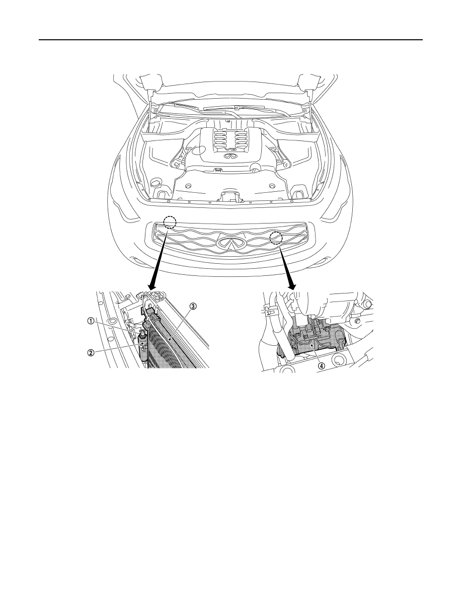
Component Parts Location
INFOID:0000000005249935
1.
Refrigerant pressure sensor
2.
Liquid tank
3.
Condenser
4.
Compressor
JSIIA1386ZZ
REFRIGERATION SYSTEM
HA-63
< SYSTEM DESCRIPTION >
[VK50VE]
C
D
E
F
G
H
J
K
L
M
A
B
HA
N
O
P
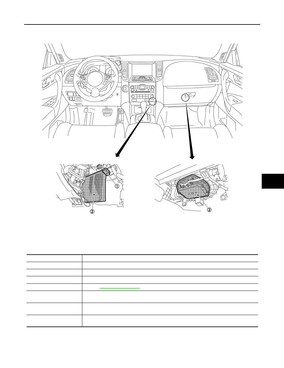
Component Description
INFOID:0000000005249936
1.
Expansion valve
2.
Evaporator
3.
Blower motor
JSIIA1279ZZ
Component
Description
Compressor
Intakes, compresses, and discharges refrigerant, to circulate refrigerant inside the refrigerant cycle.
Condenser
Cools refrigerant discharged from compressor, and transforms it to liquid refrigerant.
Liquid tank
Eliminates foreign matter in refrigerant, and stores temporarily liquid refrigerant.
Refrigerant pressure sensor
Refer to
Expansion valve
Transforms high-pressure liquid refrigerant to mist form low-pressure liquid refrigerant by drawing
function.
Evaporator
The mist form liquid refrigerant transforms to gas by evaporation by the air conveyed from blower
motor. The air is cooled by the heat by evaporation.
Blower motor
Takes in air in the vehicle or fresh outside air, provides it forcedly to the air conditioner, and conveys
it inside the vehicle.
HA-64
< SYMPTOM DIAGNOSIS >
[VK50VE]
REFRIGERATION SYSTEM SYMPTOMS
SYMPTOM DIAGNOSIS
REFRIGERATION SYSTEM SYMPTOMS
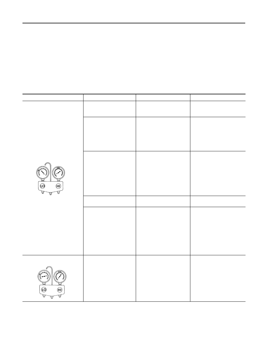
Trouble Diagnosis For Unusual Pressure
INFOID:0000000005249937
Diagnose using a manifold gauge whenever system’s high and/or low side pressure(s) is/are unusual. The
marker above the gauge scale in the following tables indicates the standard (usual) pressure range. Refer to
above table (Ambient air temperature-to-operating pressure table) since the standard (usual) pressure, how-
ever, differs from vehicle to vehicle.
Symptom Table
INFOID:0000000005249938
Gauge indication
Refrigerant cycle
Probable cause
Corrective action
Both high- and low-pressure sides
are too high.
The pressure returns to nor-
mal is reduced soon after wa-
ter is splashed on condenser.
Excessive refrigerant charge in
refrigeration cycle.
Reduce refrigerant until speci-
fied pressure is obtained.
Air suction by cooling fan is in-
sufficient.
Insufficient condenser cooling
performance.
↓
1.
Condenser fins are
clogged.
2.
Improper fan rotation of
cooling fan.
• Clean condenser.
• Check and repair cooling fan
if necessary.
• Low-pressure pipe is not
cold.
• When compressor is
stopped, high-pressure
reading quickly drops by
approximately 196 kPa (2
kg/cm
2
, 28 psi). It then de-
creases gradually thereaf-
ter.
Poor heat exchange in con-
denser
(After compressor operation
stops, high-pressure decreas-
es too slowly).
↓
Air in refrigeration cycle.
Evacuate repeatedly and re-
charge system.
Engine tends to overheat.
Engine cooling systems mal-
function.
Check and repair each engine
cooling system.
• An area of the low-pressure
pipe is colder than areas
near the evaporator outlet.
• Low-pressure pipe is some-
times covered with frost.
• Excessive liquid refrigerant
on low-pressure side.
• Excessive refrigerant dis-
charge flow.
• Expansion valve is open a lit-
tle compared with the speci-
fication.
↓
Improper expansion valve ad-
justment.
Replace expansion valve.
High-pressure side is too high and
low-pressure side is too low.
Upper side of condenser and
high-pressure side are hot,
however, liquid tank is not so
hot.
High-pressure tube or parts lo-
cated between compressor
and condenser are clogged or
crushed.
• Check and repair or replace
malfunctioning parts.
• Check lubricant for contami-
nation.
AC359A
AC360A
Нет комментариевНе стесняйтесь поделиться с нами вашим ценным мнением.
Текст