Infiniti FX35, FX50 (S51). Manual — part 1136
BLOWER UNIT
HA-57
< REMOVAL AND INSTALLATION >
[VQ35HR]
C
D
E
F
G
H
J
K
L
M
A
B
HA
N
O
P
BLOWER UNIT
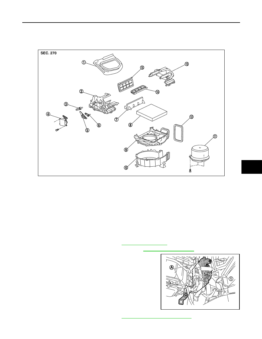
Exploded View
INFOID:0000000005249924
BLOWER UNIT
BLOWER UNIT : Removal and Installation
INFOID:0000000005249925
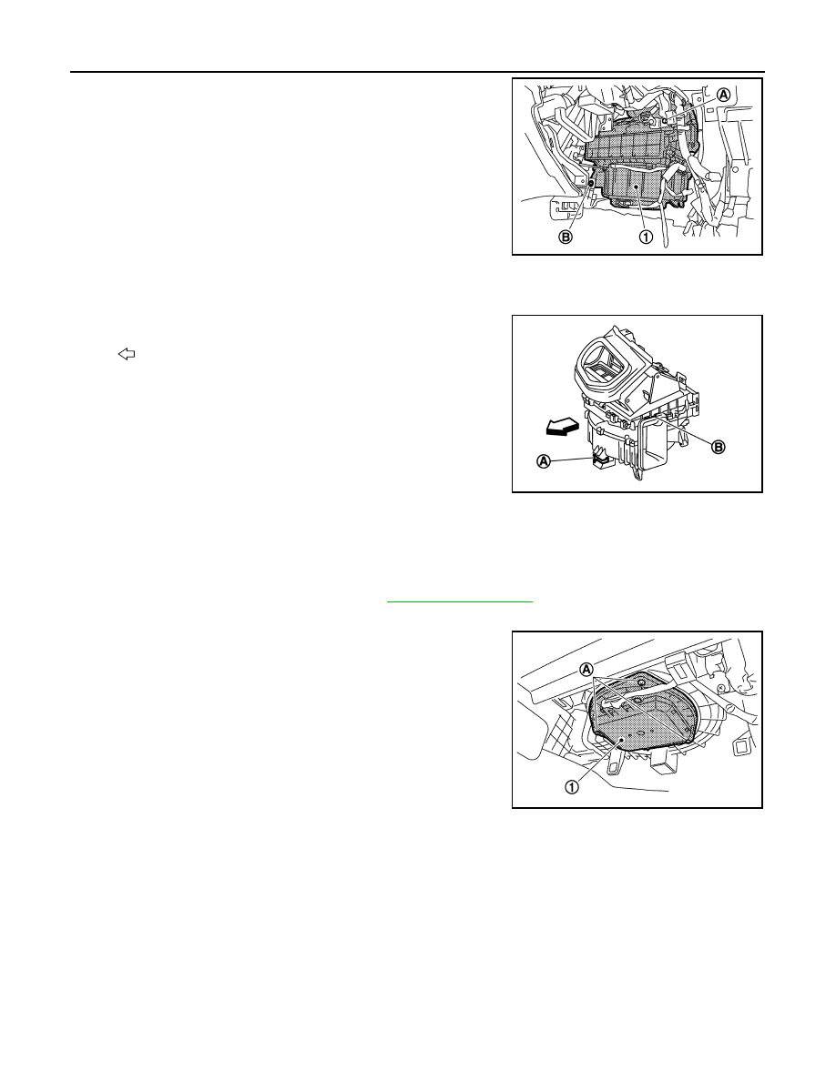
REMOVAL
1.
Remove instrument lower panel RH. Refer to
.
2.
Disconnect AWD control unit connector (AWD). Refer to
3.
Disconnect ECM (1) connectors.
4.
Remove mounting nuts (A), and then remove ECM with bracket
attached.
5.
Remove power steering control unit. Refer to
STC-27, "Removal and Installation"
.
6.
Disconnect intake door motor connector and blower motor connector.
1.
Adapter
2.
Intake box (right)
3.
Intake door lever 2
4.
Intake door motor
5.
Intake door link
6.
Intake door lever 1
7.
Filter cover
8.
In-cabin microfilter
9.
Intake upper case
10. Intake lower case
11.
Blower motor assembly
12. Seal
13. Intake box (left)
14.
Intake door 1
15. Intake door 2
JSIIA0009ZZ
JSIIA1302ZZ
HA-58
< REMOVAL AND INSTALLATION >
[VQ35HR]
BLOWER UNIT
7.
Remove mounting bolt (A) and screw (B), from blower unit (1).
8.
Remove blower unit.
CAUTION:
Move blower unit rightward, and remove locating pin (1
part) and joint. Then remove blower unit downward.
INSTALLATION
Installation is basically the reverse order of removal.
CAUTION:
Make sure locating pin (A) and joint (B) are securely inserted.
BLOWER MOTOR
BLOWER MOTOR : Removal and Installation
INFOID:0000000005249926
REMOVAL
1.
Remove instrument lower cover RH. Refer to
2.
Disconnect blower motor connector.
3.
Remove mounting screws (A), and then remove blower motor
(1).
INSTALLATION
Installation is basically the reverse order of removal.
JSIIA1303ZZ
:
Vehicle front
JSIIA0008ZZ
JSIIA1304ZZ
SERVICE DATA AND SPECIFICATIONS (SDS)
HA-59
< SERVICE DATA AND SPECIFICATIONS (SDS)
[VQ35HR]
C
D
E
F
G
H
J
K
L
M
A
B
HA
N
O
P
SERVICE DATA AND SPECIFICATIONS (SDS)
SERVICE DATA AND SPECIFICATIONS (SDS)
Compressor
INFOID:0000000005249927
Lubricant
INFOID:0000000005249928
Refrigerant
INFOID:0000000005249929
Engine Idling Speed
INFOID:0000000005249930
Belt Tension
INFOID:0000000005249931
.
Model
Calsonic Kansei make
CSE-617
Type
Variable displacement swash plate
Displacement
cm
3
(cu in)/rev
Max.
170 (10.4)
Number of cylinders
6
Cylinder bore
×
stroke (Max.)
mm (in.)
34.8 (1.37)
×
29.8 (1.17)
Direction of rotation
Clockwise (viewed from clutch)
Drive belt
Poly V
Disc to pulley clearance
mm (in.)
Standard
0.3 – 0.6 (0.012 – 0.024)
Name
NISSAN A/C System Oil Type S (DH-PS)
Capacity
m
(US fl oz, lmp fl oz)
Total in system
150 (5.07, 5.3)
Compressor (service part) charging
amount
150 (5.07, 5.3)
Type
HFC-134a (R-134a)
Capacity
kg (lb)
0.55 (1.21)

HA-60
< BASIC INSPECTION >
[VK50VE]
DIAGNOSIS AND REPAIR WORKFLOW
BASIC INSPECTION
DIAGNOSIS AND REPAIR WORKFLOW
Work Flow
INFOID:0000000005249932
DETAILED FLOW
1.
LISTEN TO CUSTOMER COMPLAINT
Listen to customer complaint. (Get detailed information about the conditions and environment when the symp-
tom occurs.)
>> GO TO 2.
2.
VERIFY THE SYMPTOM WITH OPERATIONAL CHECK
Verify the symptom with operational check. Refer to
HAC-5, "WITHOUT ACCS : Description & Inspection"
(WITHOUT ACCS) or
HAC-8, "WITH ACCS : Description & Inspection"
(WITH ACCS).
>> GO TO 3.
3.
GO TO APPROPRIATE TROUBLE DIAGNOSIS
Go to appropriate trouble diagnosis [Refer to
HAC-154, "Diagnosis Chart By Symptom"
>> GO TO 4.
4.
REPAIR OR REPLACE
Repair or replace the specific parts.
>> GO TO 5.
5.
FINAL CHECK
Final check.
Is the inspection result normal?
YES
>> INSPECTION END
NO
>> GO TO 3.
Нет комментариевНе стесняйтесь поделиться с нами вашим ценным мнением.
Текст