Infiniti FX35, FX50 (S51). Manual — part 564
MAIN SHAFT
DLN-91
< UNIT DISASSEMBLY AND ASSEMBLY >
[TRANSFER: ETX13C]
C
E
F
G
H
I
J
K
L
M
A
B
DLN
N
O
P
8.
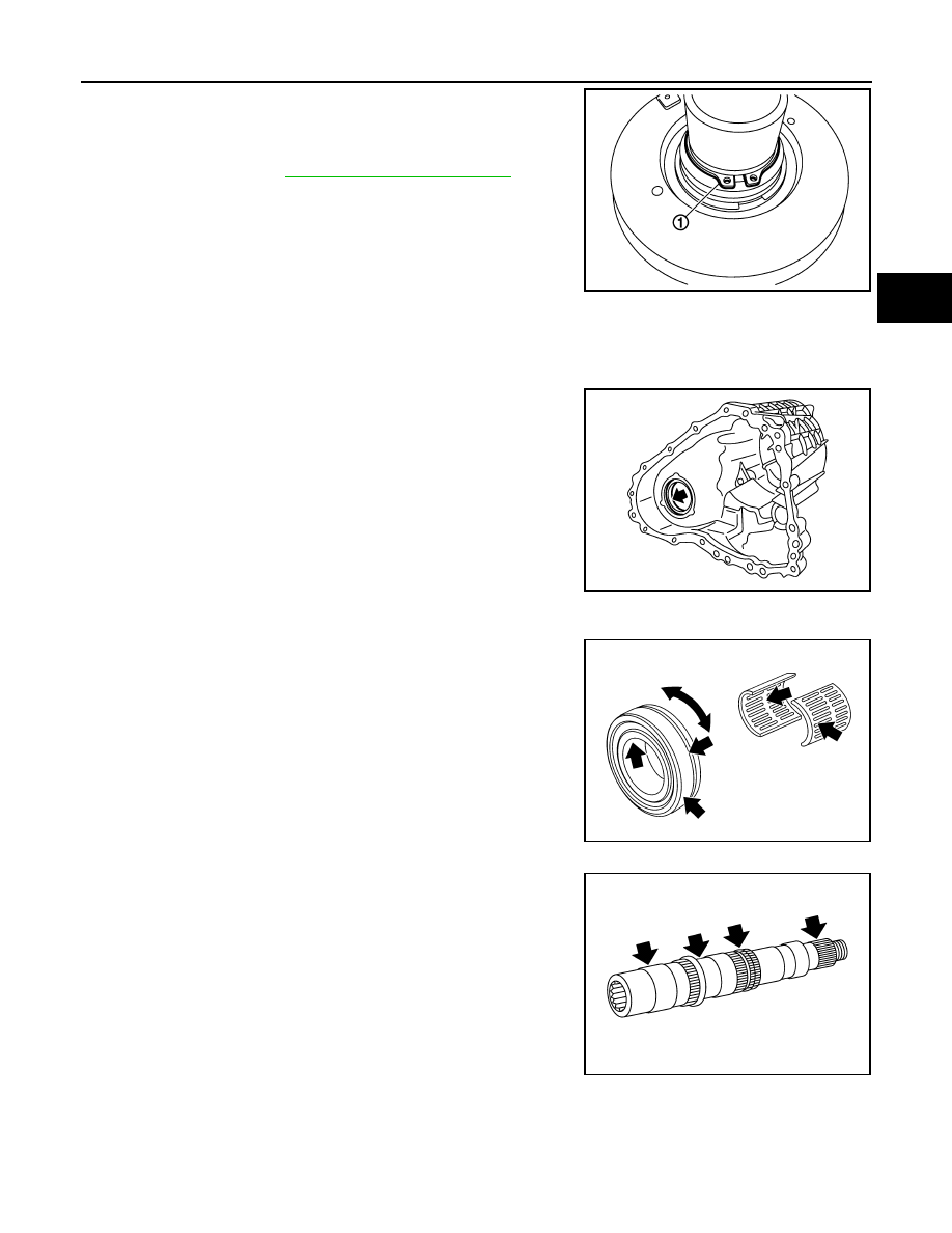
Install snap ring (1) to main shaft.
CAUTION:
Never reuse snap ring.
9.
Install main shaft assembly to rear case, then install front case
and rear case. Refer to
VQ35HR : Inspection
INFOID:0000000005525035
Check items below. If necessary, replace them with new ones.
CASES
• Contact surfaces of bearing for wear, damage, etc.
• Damage and cracks of case.
BEARING
Damage and rough rotation of bearing.
SHAFT
Damage, peeling, dent, uneven wear, bending, etc. of shaft.
GEARS AND CHAIN
JPDIE0137ZZ
JPDIE0120ZZ
PDIA0300E
JPDIE0143ZZ
DLN-92
< UNIT DISASSEMBLY AND ASSEMBLY >
[TRANSFER: ETX13C]
MAIN SHAFT
• Excessive wear, damage, peeling, etc. of gear and chain.
• Cracks, damage, wear, etc of drive chain.
VK50VE
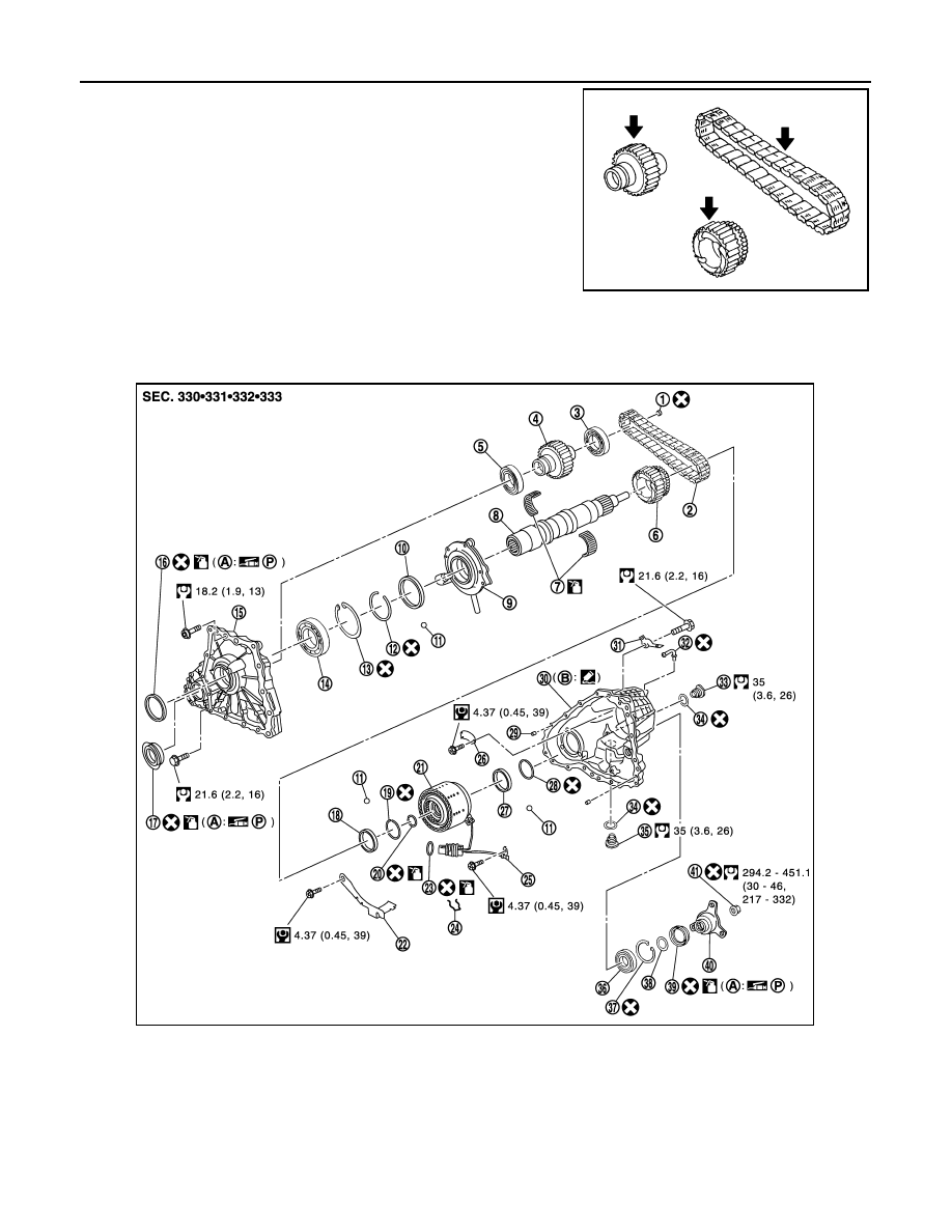
VK50VE : Exploded View
INFOID:0000000005249129
JPDIE0136ZZ
1.
Plug
2.
Drive chain
3.
Front drive shaft rear bearing
4.
Front drive shaft
5.
Front drive shaft front bearing
6.
Sprocket
7.
Needle bearing
8.
Main shaft
9.
Oil pump
10. Spacer
11.
Steel ball
12. Snap ring
13. Snap ring
14. Main shaft bearing
15. Front case
16. Main shaft oil seal
17. Front oil seal
18. Spacer
19. Snap ring
20. Circlip
21. Electric controlled coupling
JPDIE0196GB
MAIN SHAFT
DLN-93
< UNIT DISASSEMBLY AND ASSEMBLY >
[TRANSFER: ETX13C]
C
E
F
G
H
I
J
K
L
M
A
B
DLN
N
O
P
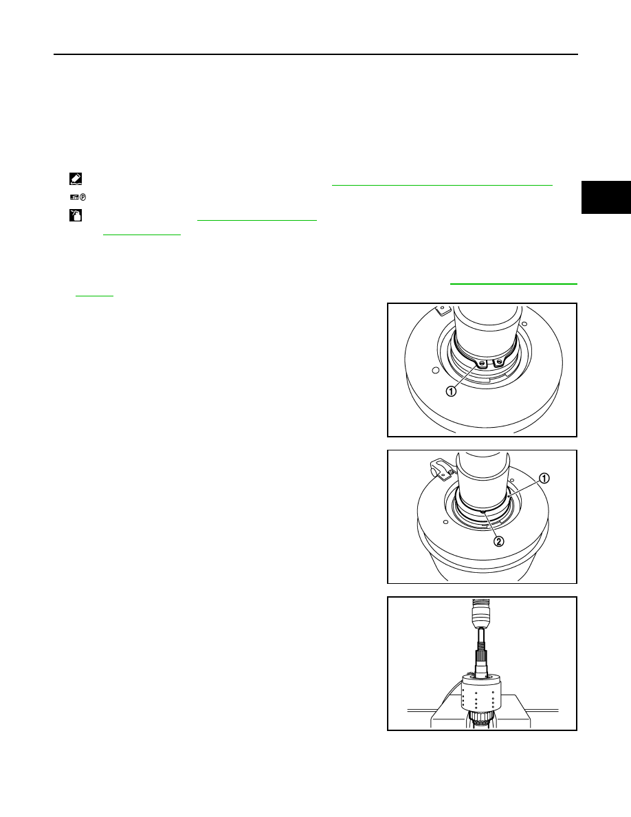
VK50VE : Disassembly
INFOID:0000000005249130
1.
Separate front case and rear case, then remove main shaft assembly. Refer to
.
2.
Remove snap ring (1) from main shaft.
3.
Remove spacer (1) and steel ball (2) from main shaft.
CAUTION:
Be careful not to drop the steel ball.
4.
Using a press, remove electric controlled coupling from main
shaft.
22. Oil cover
23. O-ring
24. Retainer
25. Transfer fluid temperature sensor
26. Baffle plate
27. Spacer
28. Snap ring
29. Dowel pin
30. Rear case
31. Harness bracket
32. Breather tube
33. Filler plug
34. Gasket
35. Drain plug
36. Rear bearing
37. Snap ring
38. Spacer
39. Rear oil seal
40. Companion flange
41. Self-lock nut
A.
Oil seal lip
B.
Matching surface
: Apply Genuine Anaerobic Liquid Gasket or equivalent. Refer to
GI-16, "Recommended Chemical Products and Sealants"
.
: Apply petroleum jelly.
: Apply transfer fluid. Refer to
MA-12, "Fluids and Lubricants"
Refer to
for symbols not described above.
JPDIE0137ZZ
JPDIE0124ZZ
JPDIE0125ZZ
DLN-94
< UNIT DISASSEMBLY AND ASSEMBLY >
[TRANSFER: ETX13C]
MAIN SHAFT
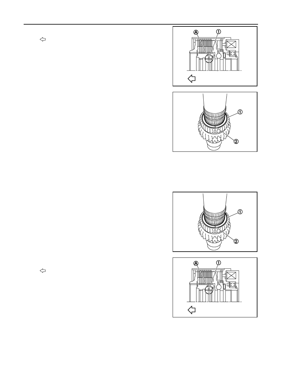
5.
Remove circlip (1) from notch (A) of electric controlled coupling.
CAUTION:
• Never remove the circlip from the electric controlled cou-
pling rear side.
• Never damage electric control coupling spline, bush, etc.
6.
Remove snap ring from main shaft.
7.
Remove spacer (1) and steel ball (2) from main shaft.
CAUTION:
Be careful not to drop the steel ball.
8.
Remove sprocket from main shaft.
9.
Remove needle bearing from main shaft.
VK50VE : Assembly
INFOID:0000000005249131
1.
Install needle bearing to main shaft.
CAUTION:
Apply transfer fluid to the periphery of needle bearing.
2.
Install sprocket to main shaft.
3.
Install spacer (1) and steel ball (2) to main shaft.
CAUTION:
Be careful not to drop the steel ball.
4.
Install snap ring to main shaft.
CAUTION:
Never reuse snap ring.
5.
Install circlip (1) to notch (A) of the electric controlled coupling.
CAUTION:
• Never install the circlip to the notches other than notch
(A).
• Never install the circlip from the electric controlled cou-
pling rear side.
• Never reduce the outer diameter of circlip to less than
43.2 mm (1.701 in).
• Never damage electric control coupling spline, bush, etc.
• Never reuse circlip.
6.
Install electric controlled coupling to main shaft.
CAUTION:
Securely insert it until locked.
: Front side
JSDIA0858ZZ
JSDIA0796ZZ
JSDIA0796ZZ
:Front side
JSDIA0858ZZ
Нет комментариевНе стесняйтесь поделиться с нами вашим ценным мнением.
Текст