Infiniti FX35, FX50 (S51). Manual — part 1896
WCS-4
< BASIC INSPECTION >
DIAGNOSIS AND REPAIR WORKFLOW
Are self-diagnosis results normal?
YES
>> GO TO 4.
NO
>> GO TO 5.
4.
NARROW DOWN MALFUNCTIONING PARTS BY SYMPTOM DIAGNOSIS
Perform symptom diagnosis and narrow down the malfunctioning parts.
>> GO TO 5.
5.
REPAIR OR REPLACE MALFUNCTIONING PARTS
Repair or replace malfunctioning parts.
NOTE:
If DTC is displayed, erase DTC after repair or replace malfunctioning parts.
>> GO TO 6.
6.
FINAL CHECK
Check that the warning buzzer in the combination meter operates normally.
Does it operate normally?
YES
>> INSPECTION END
NO
>> GO TO 1.

WCS
WARNING CHIME SYSTEM
WCS-5
< SYSTEM DESCRIPTION >
C
D
E
F
G
H
I
J
K
L
M
B
A
O
P
SYSTEM DESCRIPTION
WARNING CHIME SYSTEM
WARNING CHIME SYSTEM
WARNING CHIME SYSTEM : System Diagram
INFOID:0000000005524699
WARNING CHIME SYSTEM : System Description
INFOID:0000000005524700
COMBINATION METER
• The buzzer (1) for warning chime system is installed in the combi-
nation meter.
• The buzzer sounds when the combination meter receives buzzer
output signal from each unit through unified meter and A/C amp.
UNIFIED METER AND A/C AMP.
The unified meter and A/C amp. transmits the buzzer output signal received from BCM with CAN communica-
tion line to the combination meter.
BCM
BCM receives signals from various units and transmits a buzzer output signal to the unified meter and A/C
amp. with CAN communication line if it judges that the warning buzzer should be activated.
BCM warning function list
JSNIA0500GB
JPNIA0764ZZ
Warning functions
Signal name
Light reminder warning chime
• Lighting switch position signal
• Door switch signal
Seat belt warning chime
Seat belt buckle switch signal

WCS-6
< SYSTEM DESCRIPTION >
WARNING CHIME SYSTEM
WARNING CHIME SYSTEM : Component Parts Location
INFOID:0000000005524701
WARNING CHIME SYSTEM : Component Description
INFOID:0000000005524702
1.
BCM
2.
ABS actuator and electric unit (con-
trol unit)
3.
Unified meter and A/C amp.
4.
Front door switch (driver side)
5.
Combination switch
(Lighting switch)
6.
Parking brake switch
7.
Seat belt buckle switch (driver side)
8.
Combination meter
A.
Dash side lower (passenger side)
B.
Hoodledge cover (LH)
C.
Behind cluster lid C
JPNIA1105ZZ
Unit
Description
Combination meter
• Receives a buzzer output signal from the unified meter and A/C amp. and sounds the buzzer.
• Judges whether the parking brake is released from the vehicle speed signal received from the
unified meter and A/C amp. with CAN communication line and the parking brake switch signal
from the parking brake switch, and sounds the buzzer if necessary.
Unified meter and A/C amp.
• Receives the seat belt buckle switch signal from the seat belt buckle switch and transmits it to
BCM with CAN communication line.
• Receives a buzzer output signal from BCM with CAN communication line and transmits it to
the combination meter by means of communication line.
BCM
Transmits signals provided by various units and switches to the unified meter and A/C amp. with
CAN communication line.
ABS actuator and electric unit
(control unit)
Transmits the vehicle speed signal to unified meter and A/C amp. with CAN communication line.
Seat belt buckle switch (driver
side)
Transmits the seat belt buckle switch signal to the unified meter and A/C amp.
WCS
WARNING CHIME SYSTEM
WCS-7
< SYSTEM DESCRIPTION >
C
D
E
F
G
H
I
J
K
L
M
B
A
O
P
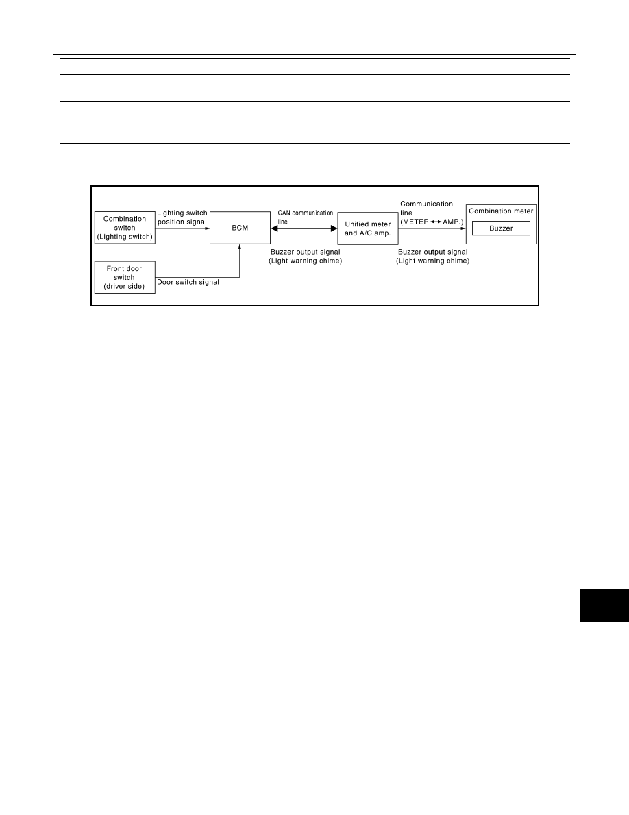
LIGHT REMINDER WARNING CHIME
LIGHT REMINDER WARNING CHIME : System Diagram
INFOID:0000000005524703
LIGHT REMINDER WARNING CHIME : System Description
INFOID:0000000005524704
DESCRIPTION
With ignition switch in OFF or ACC position, driver door open, and lighting switch in 1ST or 2ND position, the
light reminder warning chime will sound.
• BCM detects ignition switch in OFF or ACC position, front door switch (driver side) ON, and lighting switch in
1ST or 2ND position. And then transmits buzzer output signal (light reminder warning chime) to unified meter
and A/C amp. with CAN communication line.
• Unified meter and A/C amp. transmits buzzer output signal (light reminder warning chime) to combination
meter with communication line.
• When combination meter receives buzzer output signal (light reminder warning chime), it sounds the buzzer.
WARNING OPERATION CONDITIONS
If all of the following conditions are fulfilled.
• Lighting switch is at 1st or 2nd position
• Ignition switch is at OFF or ACC
• Front door switch (driver side) is ON
WARNING CANCEL CONDITIONS
Warning is canceled if any of the following conditions is fulfilled.
• Lighting switch OFF
• Ignition switch ON
• Front door switch (driver side) is OFF
Combination switch
(Lighting switch)
Transmits the lighting switch position signal to BCM.
Front door switch
(driver side)
Transmits the door switch signal to BCM.
Parking brake switch
Transmits the parking brake switch signal to the combination meter.
Unit
Description
JSNIA0167GB
Нет комментариевНе стесняйтесь поделиться с нами вашим ценным мнением.
Текст