Infiniti FX35, FX50 (S51). Manual — part 1371
MWI
MWI-3
C
D
E
F
G
H
I
J
K
L
M
B
A
O
P
UNIFIED METER AND A/C AMP. . . . . . ..
Reference Value . . . . . . . . . . . . . .
Wiring Diagram - METER - . . . . . . . . ...
Fail-Safe . . . . . . . . . . . . . . . .
DTC Index . . . . . . . . . . . . . . . .
IPDM E/R (INTELLIGENT POWER DISTRI-
BUTION MODULE ENGINE ROOM) . . . ...
Reference Value . . . . . . . . . . . . ...
Wiring Diagram - IPDM E/R - . . . . . . . .
Fail-safe . . . . . . . . . . . . . . . .
DTC Index . . . . . . . . . . . . . . .
SYMPTOM DIAGNOSIS . . . . . . .
THE FUEL GAUGE POINTER DOES NOT
MOVE . . . . . . . . . . . . . . . ...
Description . . . . . . . . . . . . . . .
Diagnosis Procedure . . . . . . . . . . . .
THE METER CONTROL SWITCH IS INOPER-
ATIVE . . . . . . . . . . . . . . . ...
Description . . . . . . . . . . . . . . .
Diagnosis Procedure . . . . . . . . . . . .
THE TRIP A/B RESET SWITCH IS INOPERA-
TIVE . . . . . . . . . . . . . . . . ..
Description . . . . . . . . . . . . . . .
Diagnosis Procedure . . . . . . . . . . . .
THE OIL PRESSURE WARNING LAMP
DOES NOT TURN ON . . . . . . . . . ..
Description . . . . . . . . . . . . . . .
Diagnosis Procedure . . . . . . . . . . . .
THE OIL PRESSURE WARNING LAMP
DOES NOT TURN OFF . . . . . . . . .
Description . . . . . . . . . . . . . . .
Diagnosis Procedure . . . . . . . . . . . .
Description . . . . . . . . . . . . . . .
Diagnosis Procedure . . . . . . . . . . . .
Description . . . . . . . . . . . . . . .
Diagnosis Procedure . . . . . . . . . . . .
THE DOOR OPEN WARNING CONTINUES
DISPLAYING, OR DOES NOT DISPLAY . .
Description . . . . . . . . . . . . . . . .
Diagnosis Procedure . . . . . . . . . . . .
THE AMBIENT TEMPERATURE DISPLAY IS
INCORRECT . . . . . . . . . . . . ...
Description . . . . . . . . . . . . . . . .
Diagnosis Procedure . . . . . . . . . . . .
NORMAL OPERATING CONDITION . . . .
COMPASS . . . . . . . . . . . . . . . ...
COMPASS : Description . . . . . . . . . .
INFORMATION DISPLAY . . . . . . . . . .
INFORMATION DISPLAY : Description . . . .
PRECAUTION . . . . . . . . . . .
PRECAUTIONS . . . . . . . . . . . ...
PREPARATION . . . . . . . . . . .
PREPARATION . . . . . . . . . . . ...
Commercial Service Tools . . . . . . . . . .
REMOVAL AND INSTALLATION . . . .
COMBINATION METER . . . . . . . . .
Exploded View . . . . . . . . . . . . . ...
Removal and Installation . . . . . . . . . ...
Disassembly and Assembly . . . . . . . . ...
UNIFIED METER AND A/C AMP. . . . . ...
Exploded View . . . . . . . . . . . . . ...
Removal and Installation . . . . . . . . . ...
METER CONTROL SWITCH . . . . . . ..
Exploded View . . . . . . . . . . . . . ...
Removal and Installation . . . . . . . . . ...
TRIP A/B RESET SWITCH . . . . . . . .
Exploded View . . . . . . . . . . . . . ...
Removal and Installation . . . . . . . . . ...
COMPASS . . . . . . . . . . . . . ...
Exploded View . . . . . . . . . . . . . ...
Removal and Installation . . . . . . . . . ...
CLOCK . . . . . . . . . . . . . . .
Exploded View . . . . . . . . . . . . . ...

MWI-4
< BASIC INSPECTION >
DIAGNOSIS AND REPAIR WORKFLOW
BASIC INSPECTION
DIAGNOSIS AND REPAIR WORKFLOW
Work flow
INFOID:0000000005524548
OVERALL SEQUENCE
• Reference 1···
MWI-43, "Diagnosis Description"
.
• Reference 2···
.
• Reference 3···
MWI-58, "COMBINATION METER : Diagnosis Procedure"
.
DETAILED FLOW
1.
OBTAIN INFORMATION ABOUT SYMPTOM
Interview the customer to obtain as much information as possible about the conditions and environment under
which the malfunction occurred.
>> GO TO 2.
2.
CHECK SYMPTOM
JSNIA0542GB

MWI
DIAGNOSIS AND REPAIR WORKFLOW
MWI-5
< BASIC INSPECTION >
C
D
E
F
G
H
I
J
K
L
M
B
A
O
P
• Check the symptom based on the information obtained from the customer.
• Check that any other malfunctions are present.
>> GO TO 3.
3.
CHECK ON BOARD DIAGNOSIS OPERATION
Check that the on board diagnosis function operates. Refer to
MWI-43, "Diagnosis Description"
Does the on board diagnosis function operate normally?
YES
>> GO TO 4.
NO
>> GO TO 6.
4.
CHECK CONSULT-III SELF-DIAGNOSIS RESULTS
Connect CONSULT-III and perform self-diagnosis. Refer to
MWI-45, "CONSULT-III Function (METER/M&A)"
.
Are self-diagnosis results normal?
YES
>> GO TO 5.
NO
>> GO TO 8.
5.
NARROW DOWN THE MALFUNCTIONING PARTS BY SYMPTOM DIAGNOSIS
Perform symptom diagnosis and narrow down the malfunctioning parts.
>> GO TO 8.
6.
CHECK COMBINATION METER POWER SUPPLY AND GROUND CIRCUITS
Inspect combination meter power supply and ground circuits. Refer to
.
Is the inspection result normal?
YES
>> GO TO 7.
NO
>> GO TO 8.
7.
REPLACE COMBINATION METER
Replace combination meter.
>> GO TO 9.
8.
REPAIR OR REPLACE MALFUNCTIONING PARTS
Repair or replace the malfunctioning parts.
NOTE:
If DTC is displayed, erase DTC after repair or replace malfunctioning parts.
>> GO TO 9.
9.
FINAL CHECK
Check that the combination meter operates normally.
Do they operate normally?
YES
>> INSPECTION END
NO
>> GO TO 1.
MWI-6
< SYSTEM DESCRIPTION >
METER SYSTEM
SYSTEM DESCRIPTION
METER SYSTEM
METER SYSTEM
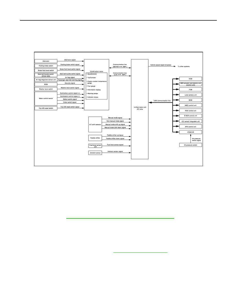
METER SYSTEM : System Diagram
INFOID:0000000005524549
METER SYSTEM : System Description
INFOID:0000000005524550
COMBINATION METER
• The combination meter retrieves the information required for controlling the operations of the meters, indica-
tor lamps/warning lamps and information display from the communication signals from the unified meter and
A/C amp. and the signals from various switches and sensors.
• The combination meter incorporates a trip computer that displays warnings and messages on the informa-
tion display according to the information received from various units.
• The combination meter incorporates a buzzer function that sounds an audible alarm with the integrated
buzzer device. Refer to
WCS-5, "WARNING CHIME SYSTEM : System Description"
for further details.
• The combination meter integrates the meter circuit check function and the segment check function that
checks the information display operation.
UNIFIED METER AND A/C AMP.
• Receives information required by the combination meter from various units via CAN communication line and
transmits it to the combination meter with communication line.
• The unified meter and A/C amp. incorporates a power saving control function that reduces the power con-
sumption according to the vehicle status. Refer to
for details.
• The unified meter and A/C amp. incorporates a diagnosis function that allows the technician to perform diag-
noses with CONSULT-III.
JSNIA2514GB
Нет комментариевНе стесняйтесь поделиться с нами вашим ценным мнением.
Текст