Infiniti FX35, FX50 (S51). Manual — part 1372

MWI
METER SYSTEM
MWI-7
< SYSTEM DESCRIPTION >
C
D
E
F
G
H
I
J
K
L
M
B
A
O
P
Between unified meter and A/C amp. and combination meter.
IPDM E/R
• IPDM E/R reads the ON/OFF signals of the oil pressure switch and transmits the oil pressure switch signal to
the unified meter and A/C amp. via BCM with the CAN communication line.
• IPDM E/R is equipped with the diagnosis function. It can perform the operation check of oil pressure warning
lamp with the auto active test and the diagnosis with CONSULT-III.
METER CONTROL FUNCTION LIST
Unit
Communication line
Input from combination meter
Output to combination meter
Unified meter
and A/C amp.
Communication line
(METER <-> AMP.)
• Parking brake switch signal
• Washer level switch signal
• Meter day/night condition signal
• Illumination control switch signal
• Refuel status signal
• Low fuel warning lamp signal
• Odo data signal
• Vehicle speed signal
• Turn indicator signal
• High beam request signal
• Position light request signal
• Engine speed signal
• Fuel level sensor signal
• Engine coolant temperature signal
• A/T CHECK indicator signal
• Oil pressure switch signal
• Door switch signal
• Buzzer output signal
• Key warning lamp signal
• AFS OFF indicator lamp signal
• Tire pressure signal
• AWD warning lamp signal
• VDC OFF indicator lamp signal
• SLIP indicator lamp signal
• IBA OFF indicator lamp signal
• ABS warning lamp signal
• Brake warning lamp signal
• Malfunction indicator lamp signal
• Master warning signal
• ICC warning lamp signal
• Lane departure warning lamp signal
• LDP ON indicator lamp signal
• RAS warning lamp signal
• Sports mode indicator lamp signal
• Meter effect signal
• Meter ring illumination request signal
Communication line
(LCD <-> AMP.)
• Average fuel consumption reset signal
• Travel time reset signal
• Possible driving distance reset signal
• Average vehicle speed reset signal
• Select switch signal
• Enter switch signal
• Trip A/B reset switch signal
• Ambient air temperature display signal
• Shift position signal
• Meter display signal
• Door switch signal
• Fuel level sensor signal
• Parking brake switch signal
• Washer level switch signal
• Charge warning signal
• Instantaneous fuel consumption display
signal
• Ambient air temperature display signal
• Average fuel consumption display signal
• Average vehicle speed display signal
• Possible driving distance display signal
• Engine speed signal
• Vehicle speed signal
• Meter effect signal
MWI-8
< SYSTEM DESCRIPTION >
METER SYSTEM
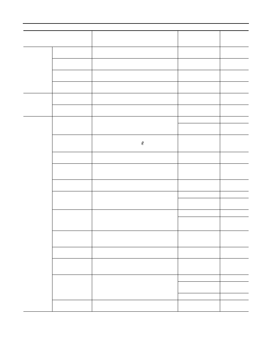
X: Applicable
ARRANGEMENT OF COMBINATION METER
System
Description
Signal source
Via unified
meter and A/C
amp.
Meter/gauge
Speedometer
Receives vehicle speed signal and indicates vehi-
cle speed.
ABS actuator and elec-
tric unit (control unit)
X
Tachometer
Receives engine speed signal and indicates en-
gine speed.
ECM
X
Fuel gauge
Receives fuel level sensor signal and indicates
fuel level.
Fuel level sensor unit
X
Engine coolant tem-
perature gauge
Receives engine coolant temperature signal and
indicates coolant temperature.
ECM
X
Warning lamp/
indicator lamp
Oil pressure warning
lamp
Receives oil pressure warning lamp signal and il-
luminates warning lamp.
IPDM E/R
X
Master warning
Illuminates according to warning output on infor-
mation display.
—
X
Information
display
Parking brake re-
lease warning
Receives parking brake switch signal and vehicle
speed signal and displays warnings.
Parking brake switch
ABS actuator and elec-
tric unit (control unit)
X
Low fuel warning
Receives fuel gauge signal and displays warning
if fuel level decreases to 14
(3 - 5/7 US gal, 3 -
1/10 Imp gal) or less.
Fuel level sensor unit
X
Low washer fluid
warning
Receives washer level switch signal and displays
warning.
Washer level switch
Low outside tempera-
ture warning
Monitors ambient sensor signal and displays
warning if ambient temperature decreases to 3
°
C
(37
°
F) or less. (If enabled)
Ambient sensor
X
Door open warning
Receives door switch signals and displays warn-
ing.
BCM
X
Instantaneous fuel
consumption
Calculates instantaneous fuel consumption based
on received vehicle speed signals and fuel con-
sumption monitor signal and displays it.
ECM
X
ABS actuator and elec-
tric unit (control unit)
X
Average fuel con-
sumption
Calculates average fuel consumption in a reset-
to-reset interval based on received vehicle speed
signals and fuel consumption monitor signal and
displays it.
ECM
X
ABS actuator and elec-
tric unit (control unit)
X
Average vehicle
speed
Calculates average vehicle speed in a reset-to-re-
set interval based on received vehicle speed sig-
nals and displays it.
ABS actuator and elec-
tric unit (control unit)
X
Travel time
Displays accumulated key switch ON time from
reset to reset.
—
X
Travel distance
Calculates accumulated travel distance in a reset-
to-reset interval based on received vehicle speed
signals and displays it.
ABS actuator and elec-
tric unit (control unit)
X
Possible driving dis-
tance
Calculates possible driving distance based on re-
ceived fuel consumption monitor signal, vehicle
speed signals and fuel level sensor signal and dis-
plays it.
ECM
X
ABS actuator and elec-
tric unit (control unit)
X
Fuel level sensor unit
X
Ambient air tempera-
ture
Corrects ambient air temperature value based on
received ambient sensor signals and displays it.
Ambient sensor
X

MWI
METER SYSTEM
MWI-9
< SYSTEM DESCRIPTION >
C
D
E
F
G
H
I
J
K
L
M
B
A
O
P
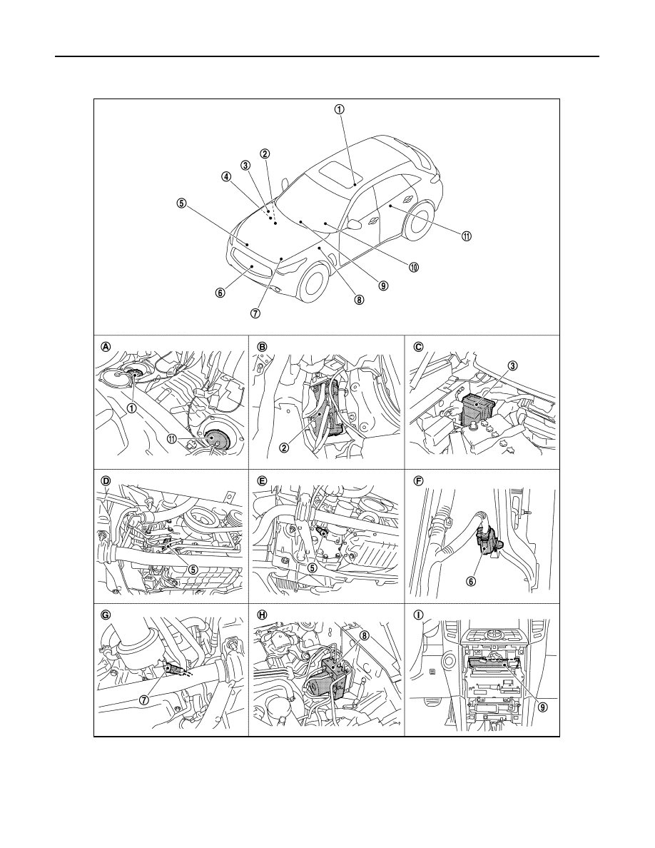
A.
VK50VE engine models
B.
VQ35HR engine models
C.
For U.S.A.
D.
Except for U.S.A.
JPNIA1107ZZ
MWI-10
< SYSTEM DESCRIPTION >
METER SYSTEM
METER SYSTEM : Component Parts Location
INFOID:0000000005524551
JPNIA1104ZZ
Нет комментариевНе стесняйтесь поделиться с нами вашим ценным мнением.
Текст