Infiniti FX35, FX50 (S51). Manual — part 599
DIFFERENTIAL ASSEMBLY
DLN-231
< UNIT DISASSEMBLY AND ASSEMBLY >
[REAR FINAL DRIVE: R200]
C
E
F
G
H
I
J
K
L
M
A
B
DLN
N
O
P
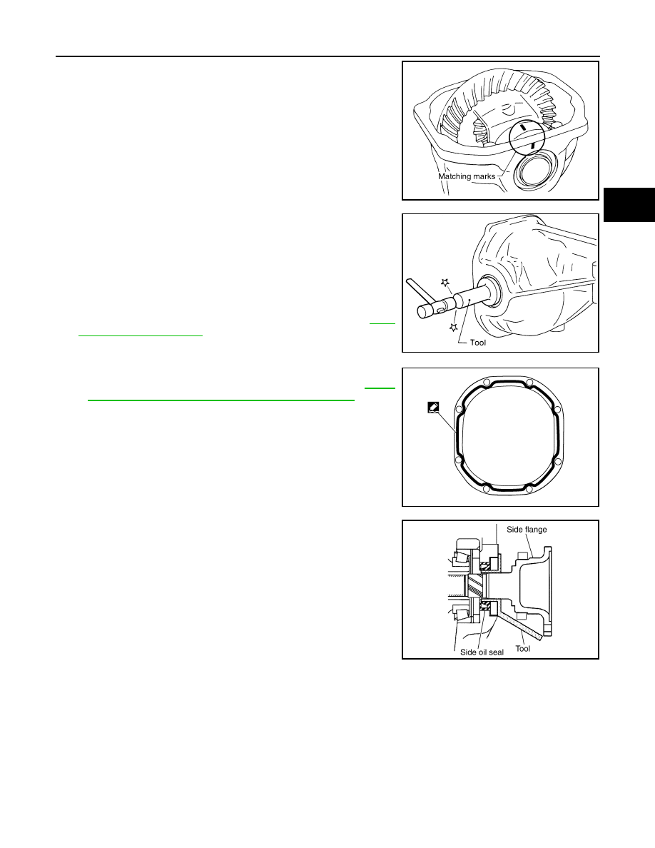
15. Align matching marks on bearing cap with that on gear carrier.
16. Install bearing caps and tighten bearing cap mounting bolts.
17. Using the drift (A) [SST: KV38100200 (J-26233)], drive side oil
seals until it becomes flush with the case end.
CAUTION:
• Never reuse oil seal.
• When installing, never incline oil seal.
• Apply multi-purpose grease onto oil seal lips, and gear oil
onto the circumference of oil seal.
18. Check and adjust drive gear runout, tooth contact, drive gear to
drive pinion backlash, and total preload torque. Refer to
Recheck above items. Readjust the above description, if neces-
sary.
19. Apply sealant (A) to mating surface of rear cover.
• Use Genuine Silicone RTV or equivalent. Refer to
"Recommended Chemical Products and Sealants"
.
CAUTION:
Remove old sealant adhering to mounting surfaces. Also
remove any moisture, oil, or foreign material adhering to
application and mounting surfaces.
20. Install rear cover on gear carrier and tighten mounting bolts.
21. Install side flange with the following procedure.
a.
Attach the protector [SST: KV38107900 (J-39352)] to side oil
seal.
b.
After the side flange is inserted and the serrated part of side
gear has engaged the serrated part of flange, remove the pro-
tector.
c.
Put a suitable drift on the center of side flange, then drive it until sound changes.
NOTE:
When installation is completed, driving sound of the side flange turns into a sound that seems to affect the
whole final drive.
SDIA1795E
SPD560
PDIA0961E
SDIA0822E
DLN-232
< UNIT DISASSEMBLY AND ASSEMBLY >
[REAR FINAL DRIVE: R200]
DIFFERENTIAL ASSEMBLY
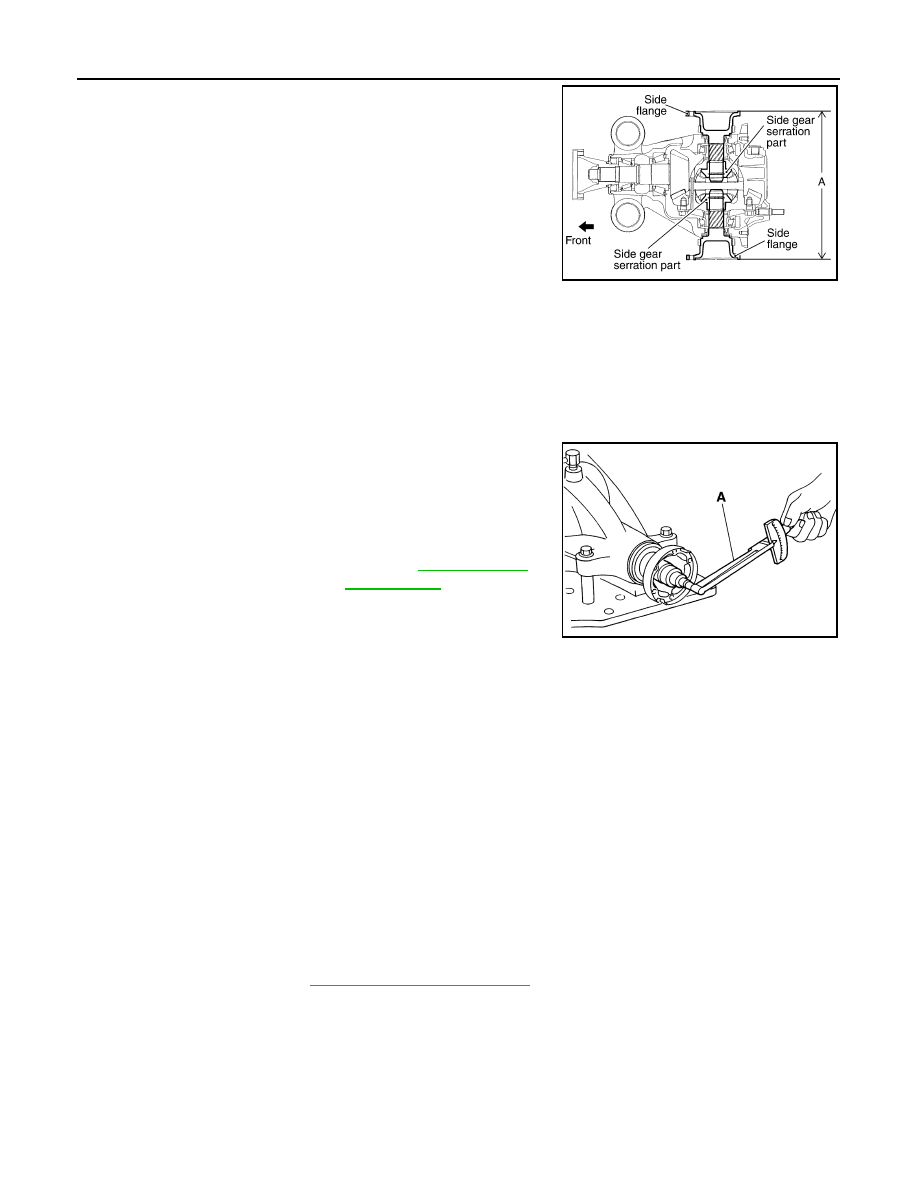
d.
Confirm that the dimension of the side flange installation mea-
surement (A) in the figure comes into the following.
AWD : Adjustment
INFOID:0000000005249245
TOTAL PRELOAD TORQUE
Before inspection and adjustment, drain gear oil.
1.
Secure final drive assembly onto an attachment [SST: KV38100800 (J-25604-01)].
2.
Remove side flanges.
3.
Rotate drive pinion back and forth 2 to 3 times to check for unusual noise and rotation malfunction.
4.
Rotate drive pinion at least 20 times to check for smooth opera-
tion of the bearing.
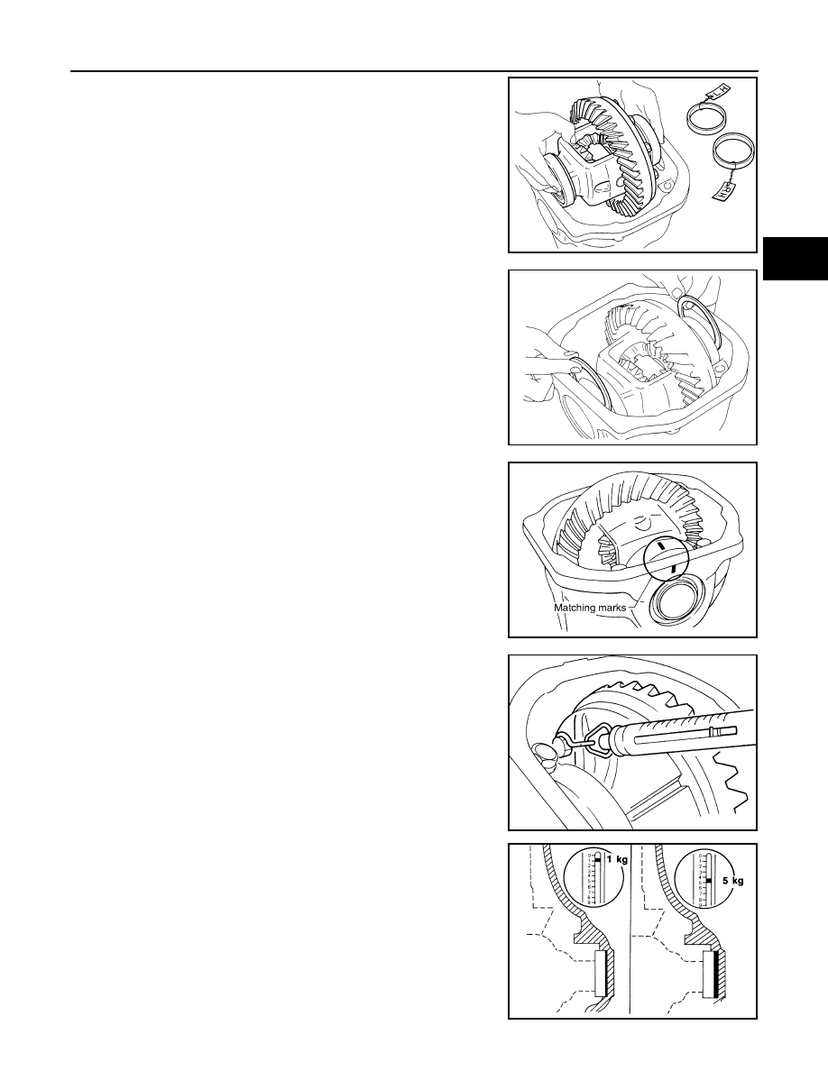
5.
Measure total preload with the preload gauge (A) [SST:
ST3127S000 (J-25765-A)].
NOTE:
Total preload torque = Pinion bearing preload torque + Side
bearing preload torque
• If measured value is out of the specification, disassemble it to check and adjust each part. Adjust the
pinion bearing preload and side bearing preload.
Adjust the pinion bearing preload first, then adjust the side bearing preload.
SIDE BEARING PRELOAD
Before inspection and adjustment, drain gear oil.
1.
Remove rear cover. Refer to
.
Standard
A
: 326 – 328 mm (12.83 – 12.91 in)
SDIA1039E
Standard
Total preload torque
: Refer to
PDIA0766J
When the preload torque is large
On pinion bearings:
Replace the collapsible spacer.
On side bearings:
Use thinner side bearing adjusting washers by the same amount to
each side.
When the preload is small
On pinion bearings:
Tighten the drive pinion lock nut.
On side bearings:
Use thicker side bearing adjusting washers by the same amount to
each side.
DIFFERENTIAL ASSEMBLY
DLN-233
< UNIT DISASSEMBLY AND ASSEMBLY >
[REAR FINAL DRIVE: R200]
C
E
F
G
H
I
J
K
L
M
A
B
DLN
N
O
P
2.
Make sure all parts are clean. Also, make sure the bearings are
well lubricated with gear oil.
3.
Place the differential case, with side bearings and bearing races
installed, into gear carrier.
4.
Insert left and right original side bearing adjusting washers in
place between side bearings and gear carrier.
5.
Install bearing caps in their correct locations and tighten bearing
cap mounting bolts.
6.
Turn the carrier several times to seat the bearings.
7.
Measure the turning torque of the carrier at the drive gear
mounting bolts with a spring gauge [SST:
—
(J-8129)].
8.
If the turning torque is outside the specification, use a thicker/
thinner side bearing adjusting washer to adjust.
CAUTION:
Select a side bearing adjusting washer for right and left
individually.
SPD527
SPD558
SDIA1795E
Standard
Specification
: 34.2 – 39.2 N (3.5 – 4.0 kg,
7.7 – 8.8 lb) of pulling force
at the drive gear bolt
SPD194A
If the turning torque is less
than the specified range:
Use a thicker thrust wash-
er.
If the turning torque is
greater than the specifica-
tion:
Use a thinner thrust wash-
er.
SPD772
DLN-234
< UNIT DISASSEMBLY AND ASSEMBLY >
[REAR FINAL DRIVE: R200]
DIFFERENTIAL ASSEMBLY
9.
Record the total amount of washer thickness required for the correct carrier side bearing preload.
DRIVE GEAR RUNOUT
1.
Remove rear cover. Refer to
.
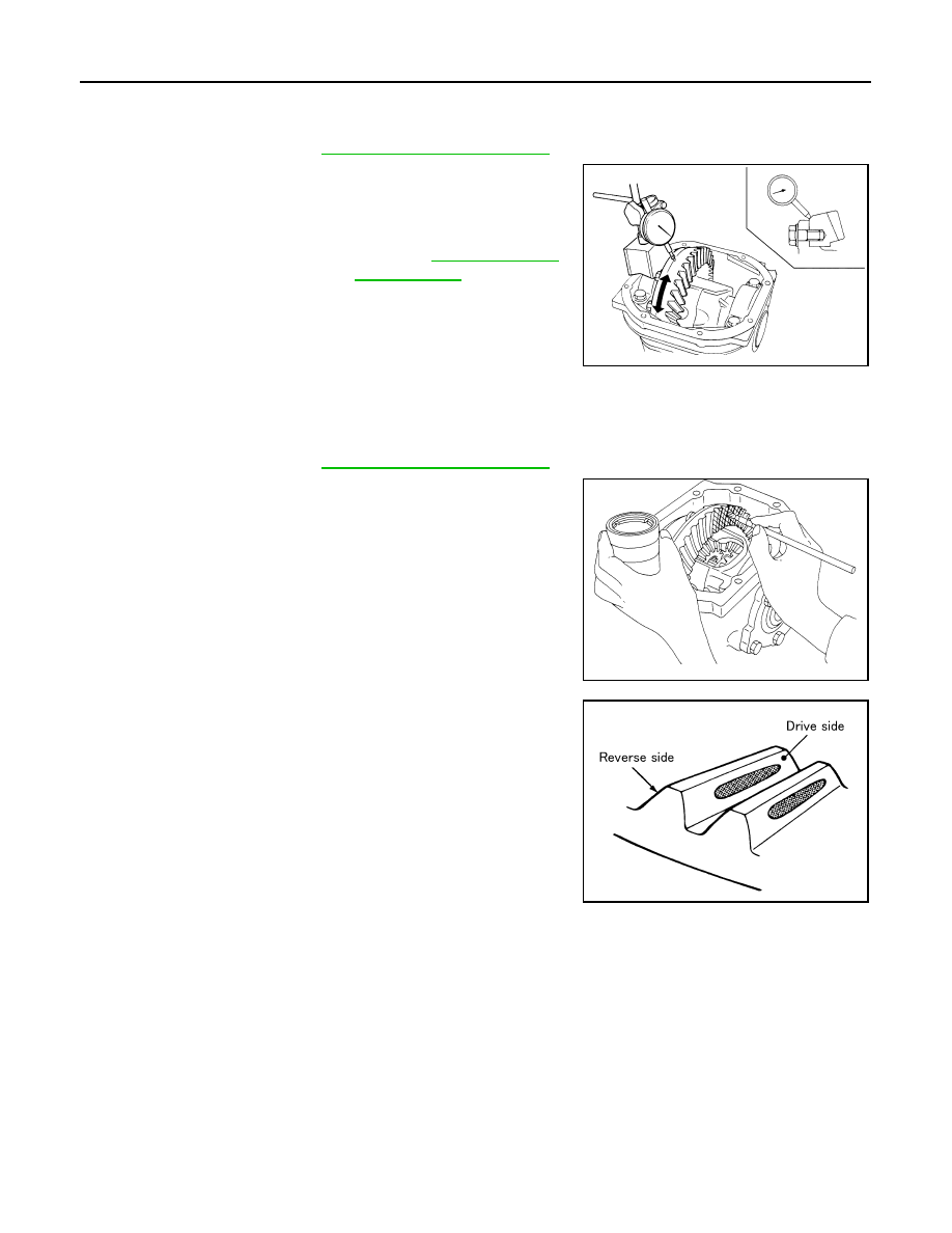
2.
Fit a dial indicator to the drive gear back face.
3.
Rotate the drive gear to measure runout.
• If the runout is outside of the repair limit, check drive gear
assembly condition; foreign material may be caught between
drive gear and differential case, or differential case or drive
gear may be deformed, etc.
CAUTION:
Replace drive gear and drive pinion gear as a set.
TOOTH CONTACT
Before inspection and adjustment, drain gear oil.
1.
Remove rear cover. Refer to
.
2.
Apply red lead to drive gear.
CAUTION:
Apply red lead to both the faces of 3 to 4 gears at 4 loca-
tions evenly spaced on drive gear.
3.
Rotate drive gear back and forth several times, check drive pin-
ion gear to drive gear tooth contact.
CAUTION:
Check tooth contact on drive side and reverse side.
Limit
Drive gear runout
: Refer to
SPD886
SPD357
SDIA0570E
Нет комментариевНе стесняйтесь поделиться с нами вашим ценным мнением.
Текст