Infiniti FX35, FX50 (S51). Manual — part 598
DIFFERENTIAL ASSEMBLY
DLN-227
< UNIT DISASSEMBLY AND ASSEMBLY >
[REAR FINAL DRIVE: R200]
C
E
F
G
H
I
J
K
L
M
A
B
DLN
N
O
P
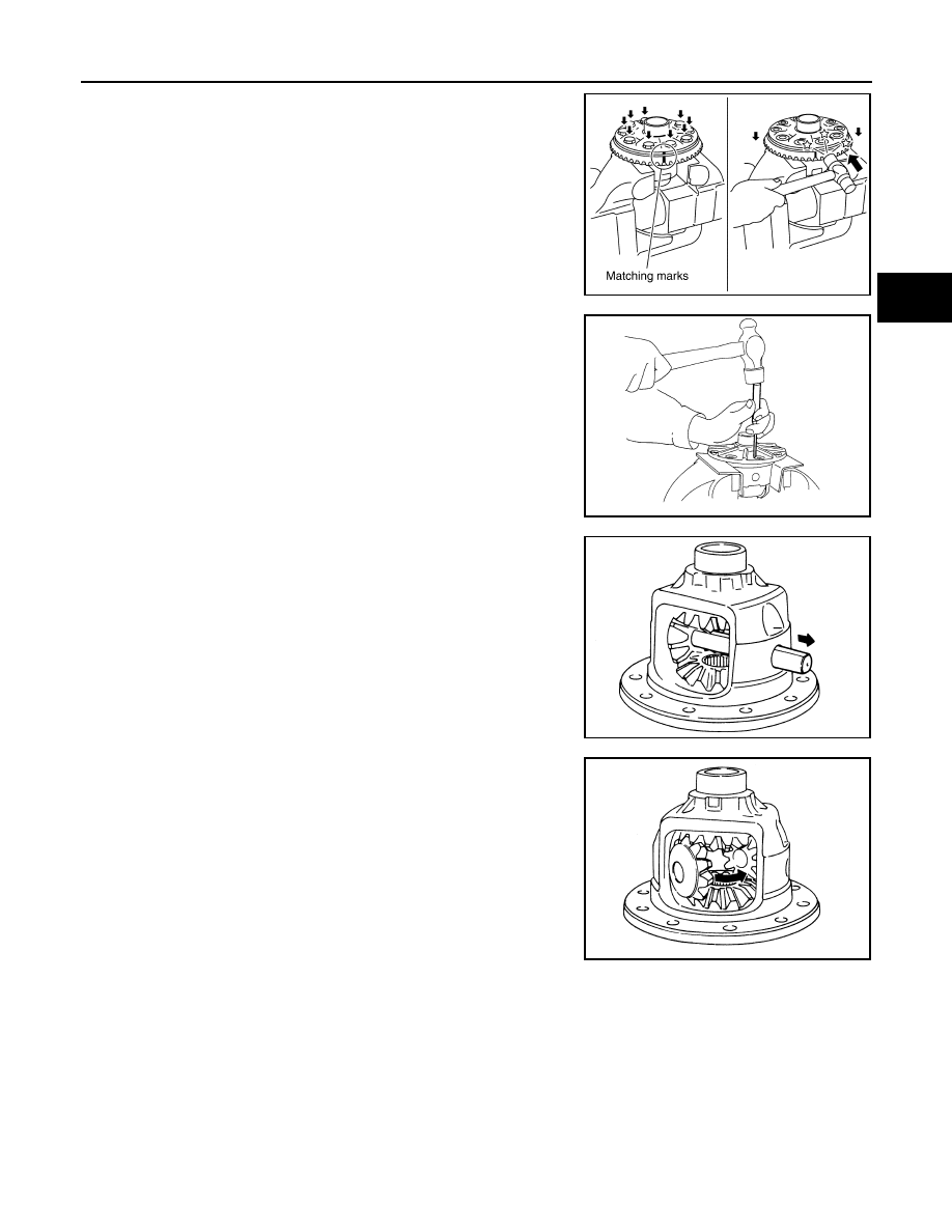
10. For proper reinstallation, paint matching marks on one differen-
tial case assembly.
CAUTION:
For matching marks, use paint. Never damage differential
case and drive gear.
11. Remove drive gear mounting bolts.
12. Tap drive gear off differential case assembly with a soft hammer.
CAUTION:
Tap evenly all around to keep drive gear from bending.
13. Remove lock pin of pinion mate shaft with a punch from drive
gear side.
14. Remove pinion mate shaft.
15. Turn pinion mate gear, then remove pinion mate gear, pinion
mate thrust washer, side gear and side gear thrust washer from
differential case.
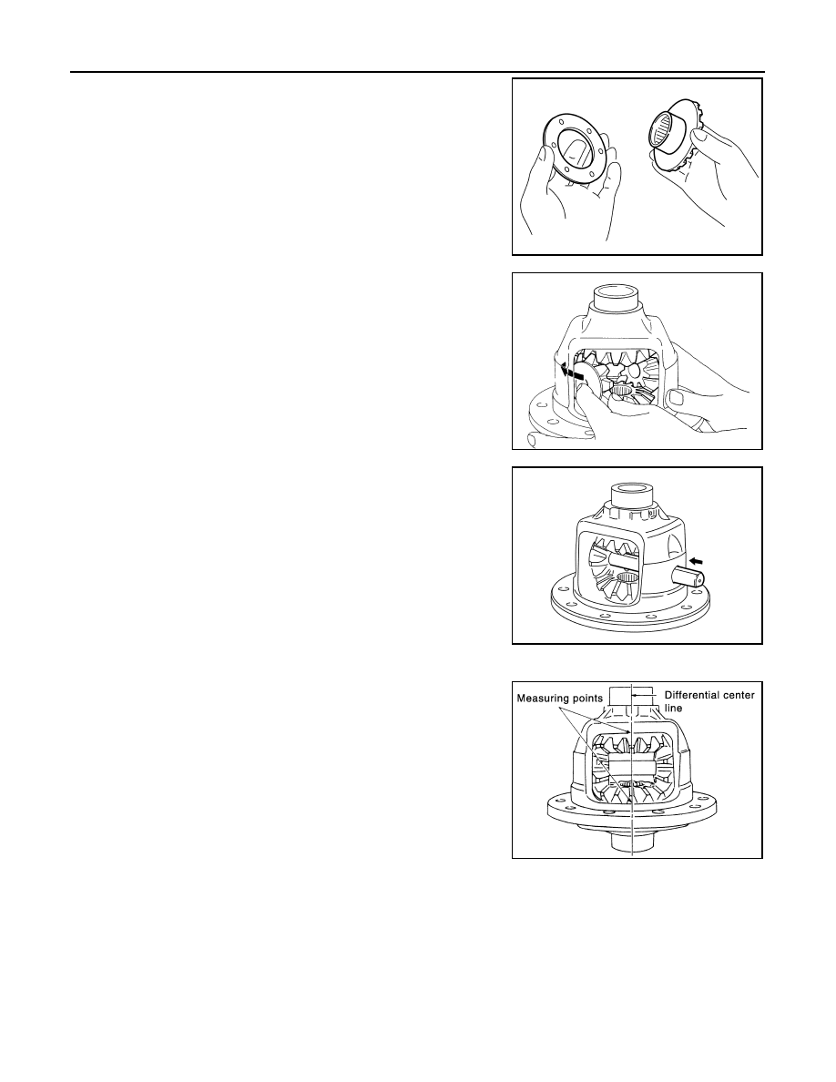
16. Remove circular clip from side gear.
CAUTION:
Never damage side gear.
AWD : Assembly
INFOID:0000000005249244
1.
Install circular clip to side gear.
CAUTION:
Never damage side gear.
PDIA0496E
PDIA0759J
SDIA0031J
SDIA0032J
DLN-228
< UNIT DISASSEMBLY AND ASSEMBLY >
[REAR FINAL DRIVE: R200]
DIFFERENTIAL ASSEMBLY
2.
Install side gear thrust washers with the same thickness as the
ones installed prior to disassembly or reinstall the old ones on
the side gears.
3.
Install side gears and thrust washers into differential case.
CAUTION:
Make sure that the circular clip is installed to side gears.
4.
Align 2 pinion mate gears in diagonally opposite positions, then
rotate and install them into differential case after installing thrust
washer to pinion mate gear.
5.
Align the lock pin holes on differential case with shaft, and install
pinion mate shaft.
6.
Measure side gear end play. If necessary, select the appropriate side gear thrust washers.
a.
Place differential case straight up so that side gear to be mea-
sured comes upward.
SDIA0193J
SDIA2025E
SDIA0195J
JPDID0205GB
DIFFERENTIAL ASSEMBLY
DLN-229
< UNIT DISASSEMBLY AND ASSEMBLY >
[REAR FINAL DRIVE: R200]
C
E
F
G
H
I
J
K
L
M
A
B
DLN
N
O
P
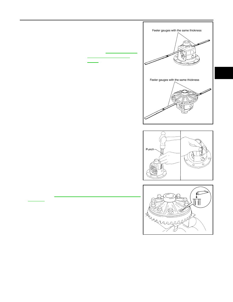
b.
Using feeler gauge, measure the clearance between side gear
back and differential case at 3 different points, while rotating
side gear. Average the 3 readings, and then measure the clear-
ance of the other side as well.
CAUTION:
To prevent side gear from tilting, insert feeler gauges with
the same thickness from both sides.
c.
If the back clearance is outside the specification, use a thicker/
thinner side gear thrust washer to adjust.
CAUTION:
Select a side gear thrust washer for right and left individu-
ally.
7.
Drive a lock pin into pinion mate shaft, using a punch.
Make sure lock pin is flush with differential case.
CAUTION:
Never reuse lock pin.
8.
Apply thread locking sealant into the thread hole of drive gear.
Use Genuine High Strength Thread Locking Sealant or equiva-
lent. Refer to
GI-16, "Recommended Chemical Products and
.
CAUTION:
Clean and degrease drive gear back and threaded holes
sufficiently.
9.
Install the drive gear to differential case.
CAUTION:
Align the matching mark of differential case and drive gear.
Standard
Side gear back clearance
: Refer to
When the back clearance
is large:
Use a thicker thrust wash-
er.
When the back clearance
is small:
Use a thinner thrust wash-
er.
PDIA0576E
SPD030
SDIA2594E
DLN-230
< UNIT DISASSEMBLY AND ASSEMBLY >
[REAR FINAL DRIVE: R200]
DIFFERENTIAL ASSEMBLY
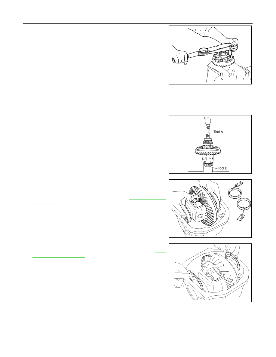
10. Tighten the mounting bolts with the following procedure.
CAUTION:
Apply anti-corrosin oil to the thread and seat of mounting
bolts.
a.
Tighten the bolts in a crisscross fashion to the specified torque.
b.
Tighten the bolts additionally to the specified angle.
CAUTION:
Check the tightening angle using the angle wrench [SST: KV10112100 (BT-8653-A)]. Never make
judgment by visual inspection.
11. Press side bearing inner races to differential case, using the drift
and the base.
CAUTION:
Never reuse side bearing inner race.
12. Install differential case assembly with side bearing outer races
into gear carrier.
13. Measure side bearing preload. If necessary, select the appropri-
ate side bearing adjusting washers. Refer to
.
14. Insert selected left and right side bearing adjusting washers in
place between side bearings and gear carrier. Refer to
Drive gear mounting
bolts tightening torque
: 78.5 N•m (8.0 kg-m, 58 ft-lb)
Drive gear mounting
bolts tightening angle
: 31 to 36 degree
A
:Puller [SST: ST33051001 (J-22888-20)]
B
: Base [SST: ST33061000 (J--2)]
SDIA0247J
SPD353
SPD527
SPD558
Нет комментариевНе стесняйтесь поделиться с нами вашим ценным мнением.
Текст