Infiniti FX35, FX50 (S51). Manual — part 410

CCS-460
< SYSTEM DESCRIPTION >
[LDW & LDP]
LANE DEPARTURE PREVENTION (LDP) SYSTEM
Reception Unit
Signal Name
Transmission Unit
Description
(Reception unit uses...)
Lane camera unit
LDP operation signal
ABS actuator and elec-
tric unit (control unit)
Detects the LDP operating condition
LDP condition signal
Detects the LDP conditions
LDP buzzer request signal
Controls the lane departure warning buzzer ac-
cording to the request
LDP meter indication request
signal
Controls the LDP ON indicator lamp and lane de-
parture warning lamp according to the request
Vehicle speed signal
Detects the vehicle speed
Front wiper status signal
Detects operation of the front wiper
Turn indicator signal
BCM
Detects operation of turn signals
Ambient temperature signal
Unified meter and A/C
amp.
Detects the ambient temperature
ABS actuator and
electric unit (control
unit)
Detected lane condition signal
Lane camera unit
Detects the lane marker condition
Lane camera status signal
Detects the lane camera status
LDW operation signal
Detects the LDW operation
Lane departure buzzer opera-
tion signal
Detects the lane departure warning buzzer opera-
tion
LDW switch signal
Detects LDW switch status
LDP ON indicator lamp signal
Detects the LDP ON indicator lamp condition
Lane departure warning lamp
signal
Detects the lane departure warning lamp condition
Snow mode switch signal
ECM
Detects the snow mode status
Accelerator pedal position sig-
nal
Detects vehicle conditions to calculate the acceler-
ation/deceleration of the vehicle
Engine speed signal
Shift position signal
TCM
Detects the transmission conditions
Output shaft revolution signal
Input speed signal
Current gear position signal
Steering angle sensor signal
Steering angle sensor
Detects the steering angle
ICC operation signal
ICC sensor integrated
unit
Detects ICC system conditions
Target approach warning signal
Buzzer output signal
LDP ON signal
Detects the LDP ON status
Turn indicator signal
BCM
Detects operation of turn signals
Front wiper request signal
Detects operation of the front wiper
Combination meter
(through unified meter
and A/C amp.)
LDP ON indicator lamp signal
Lane camera unit
Turns the LDP ON indicator lamp ON/OFF accord-
ing to the request
Lane departure warning lamp
signal
Turns the lane departure warning lamp ON/OFF
according to the request
ICC sensor integrated
unit
ICC steering switch signal
(LDP switch signal)
ECM
Detects the LDP switch status
System selection signal
AV control unit
Detects the LDP system setting status
CCS
LANE DEPARTURE PREVENTION (LDP) SYSTEM
CCS-461
< SYSTEM DESCRIPTION >
[LDW & LDP]
C
D
E
F
G
H
I
J
K
L
M
B
N
P
A
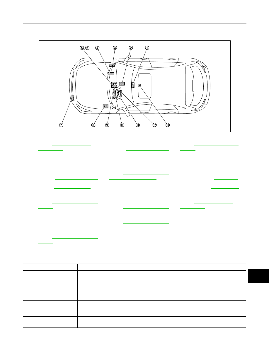
Component Parts Location
INFOID:0000000005502070
Component Description
INFOID:0000000005502071
1.
.
2.
TCM
Refer to the following.
VQ35HR:
VK50VE:
3.
BCM
Refer to
4.
ECM
Refer to the following.
VQ35HR:
VK50VE:
5.
Unified meter and A/C amp.
Refer to
6.
AV control unit
Refer to the following.
With single monitor:
With twin monitor:
7.
ICC sensor integrated unit
Refer to
.
8.
ABS actuator and electric unit (con-
trol unit)
Refer to
9.
Lane departure warning buzzer
Refer to
.
10. • LDP ON indicator lamp (Green)
• Lane departure warning lamp (Yel-
low)
11.
Steering angle sensor
Refer to
12. Steering switch
(LDP switch)
13. Yaw rate/side G sensor
.
JSOIA0156GB
Component
Description
Lane camera unit
• Detects the lane marker by the built-in camera.
• Judges the lane departure depending on the lane detection result and each signal.
• Transmits the detected lane conditions to ABS actuator and electric unit (control unit) via CAN com-
munication.
• Controls the lane departure warning buzzer, lane departure warning lamp, LDW ON indicator and
LDP ON indicator lamp.
ABS actuator and electric unit
(control unit)
• Transmits vehicle speed signal to lane camera unit via CAN communication.
• Judges necessary yaw moment depending on each signal.
• Controls the brake pressure of each wheel individually to generate the intended movement.
Lane departure warning buzz-
er
Gives a warning according to the direction from lane camera unit.

CCS-462
< SYSTEM DESCRIPTION >
[LDW & LDP]
LANE DEPARTURE PREVENTION (LDP) SYSTEM
LDP switch
(On the ICC steering switch)
Inputs the switch signal to ECM.
Combination meter
Turns the lane departure warning lamp and LDP ON indicator lamp ON/OFF according to the signals
from the lane camera unit via CAN communication (through unified meter and A/C amp.).
LDP ON indicator lamp
(Green)
Indicates LDP system status.
Lane departure warning lamp
(Yellow)
• Blinks when LDP is functioning to alert the driver.
• Stays ON when LDW/LDP system is malfunctioning.
BCM
• Transmits turn indicator signal to lane camera unit via CAN communication.
• Transmits vehicle conditions to ABS actuator and electric unit (control unit) via CAN communica-
tion.
ECM
Transmits vehicle conditions and ICC steering switch signal (LDP switch signal) to ICC sensor inte-
grated unit via CAN communication.
Unified meter and A/C amp.
Transmits ambient temperature signal to lane camera unit via CAN communication.
Steering angle sensor
Transmits steering angle sensor signal to ABS actuator and electric unit (control unit) via CAN com-
munication.
TCM
Transmits vehicle conditions to ABS actuator and electric unit (control unit) via CAN communication.
ICC sensor integrated unit
• Transmits ICC system conditions to ABS actuator and electric unit (control unit) via CAN communi-
cation.
• Transmits LDP ON signal to ABS actuator and electric unit (control unit) via CAN communication.
Yaw rate/side G sensor
Inputs detected yaw rate signal to ABS actuator and electric unit (control unit).
AV control unit
Transmits system selection signal to ICC sensor integrated unit via CAN communication.
Component
Description

CCS
DIAGNOSIS SYSTEM (LANE CAMERA UNIT)
CCS-463
< SYSTEM DESCRIPTION >
[LDW & LDP]
C
D
E
F
G
H
I
J
K
L
M
B
N
P
A
DIAGNOSIS SYSTEM (LANE CAMERA UNIT)
CONSULT-III Function (LANE CAMERA)
INFOID:0000000005502072
DESCRIPTION
CONSULT-III performs the following functions by communicating with the lane camera unit.
WORK SUPPORT
Cause of Auto-Cancel Display Item List
When LDP control is canceled under the operating condition, “CAUSE OF AUTO-CANCEL” is memorized.
• Last five cancel (system cancel) causes are displayed.
• “CAUSE OF AUTO-CANCEL” displays the number of times of ignition switch ON/OFF up to a maximum of
“39”. “39” is kept even when the number exceeds “39”. The number returns to 0 when detecting the same
cancellation causes are detected.
Select diag mode
Function
Work support
• Performs the camera aiming.
• Displays causes of automatic cancellation of the LDP function.
Self Diagnostic Result
Displays memorized DTC in the lane camera unit.
Data Monitor
Displays real-time data of lane camera unit.
Active Test
Enables operation check of electrical loads by sending driving signal to them.
Ecu Identification
Displays part number of lane camera unit.
Work support item
Function
CAUSE OF AUTO-CANCEL
Indicates causes of automatic cancellation of the LDP.
AUTO AIM
Outputs camera unit, calculates dislocation of the camera, and displays adjustment direction.
Refer to
CCS-445, "CAMERA AIMING ADJUSTMENT : Description"
.
Cause of cancellation
Description
NO RECORD
—
Operating VDC/ABS
VDC or ABS function was operated.
Vehicle dynamics
Vehicle behavior exceeds specified value.
Steering speed
Steering speed was more than the specified value in evasive direction.
End by yaw angle
Yaw angle was the end of LDP control.
Departure yaw large
Detected more than the specified value of yaw angle in departure direction.
ICC WARNING
Target approach warning of ICC system or IBA system was activated.
VDC OFF SW
VDC OFF switch was pressed.
CURVATURE
Road curve was more than the specified value.
Steering angle large
Steering angle was more than the specified value.
ICC main SW hold ON
ICC MAIN switch was held ON for more than a certain period.
Brake is operated
Brake pedal was operated.
Lateral offset
Distance of vehicle and lane was detached in lateral direction more than the specified value.
Lane marker lost
Lane camera unit lost the trace of lane marker.
Lane marker unclear
Detected lane marker was unclear.
Bank
Road bank angle was more than the specified value.
Yaw acceleration
Detected yawing speed was more than the specified value.
Deceleration large
Deceleration in a longitudinal direction was more than the specified value.
Accel is operated
Accelerator pedal was depressed.
Departure steering
Steering wheel was steered more than the specified value in departure direction.
Нет комментариевНе стесняйтесь поделиться с нами вашим ценным мнением.
Текст