Infiniti FX35, FX50 (S51). Manual — part 1881

TCM
TM-331
< ECU DIAGNOSIS INFORMATION >
[7AT: RE7R01B (VK50VE)]
C
E
F
G
H
I
J
K
L
M
A
B
TM
N
O
P
Protection Control
INFOID:0000000005250334
The TCM becomes the protection control status temporarily to protect the safety when the safety of TCM and
transmission is lost. It automatically returns to the normal status if the safety is secured.
The TCM has the following protection control.
REVERSE INHIBIT CONTROL
Intercepts the torque transmission and shift to the neutral status if the selector lever is shifted to “R” position
while the vehicle moves forward at the vehicle speed 10 km/h (7 MPH) or more.
1ST ENGINE BRAKE PROTECTION CONTROL
Controls the engine brake so as not to make effective by turning the front brake solenoid output to OFF when
each solenoid becomes the electricity pattern of 1st engine brake during driving at the vehicle speed 25 km/h
or more in any positions other than “R” position or 1GR.
TCM HIGH TEMPERATURE PROTECTION CONTROL
Limit the accelerator opening and forcibly control the vehicle to the low torque driving when the electronic sub-
strate in TCM reaches the high temperature.
P1815
Paddle
switch mal-
function
Only the paddle switch is prohibited
—
Only the paddle switch is prohibited
Gate switch
malfunction
Only the gate switch is prohibited
—
Only the gate switch is prohibited
Malfunction
of both
switches
Manual mode is prohibited
—
Manual mode is prohibited
U1000
Between
the gears of
1 - 2 - 3
• The shifting between the gears
of 1 - 2 - 3 can be performed
• Manual mode is prohibited
—
• The shifting between the gears
of 1 - 2 - 3 can be performed
• Line pressure is set to the maxi-
mum hydraulic pressure
• Manual mode is prohibited
Between
the gears of
4 - 5 -6 - 7
• Fix the gear at driving
• Manual mode is prohibited
—
P0720
and
P1721
—
Locks in 5GR
—
Locks in 5GR
DTC
Vehicle
condition
Vehicle behavior for 1st fail-safe
Vehicle behavior for 2nd fail-safe
Vehicle behavior for final fail-safe
Malfunction detection condition
Vehicle speed: 10 km/h (7 MPH) or more
Control at malfunction
Neutral
Normal return condition
• Vehicle speed: 8 km/h (5 MPH) or less
• Engine speed: 2,200 rpm or less
Vehicle behavior
• The torque transmission cannot be performed
• There is a shock just before a vehicle stop
Malfunction detection condition
• Select lever and gear: Except for “R” position and 1GR
and
• Vehicle speed: More than 25 km/h (16 MPH)
Control at malfunction
Front brake solenoid output signal; OFF
Normal return condition
Other than malfunction detection condition
Vehicle behavior
Does not exist
Malfunction detection condition
TCM electronic substrate temperature
• 145
°
C (293
°
F) and 120 seconds
or
• 150
°
C (302
°
F)
Control at malfunction
Accelerator opening: 0.5/8 or less
TM-332
< ECU DIAGNOSIS INFORMATION >
[7AT: RE7R01B (VK50VE)]
TCM
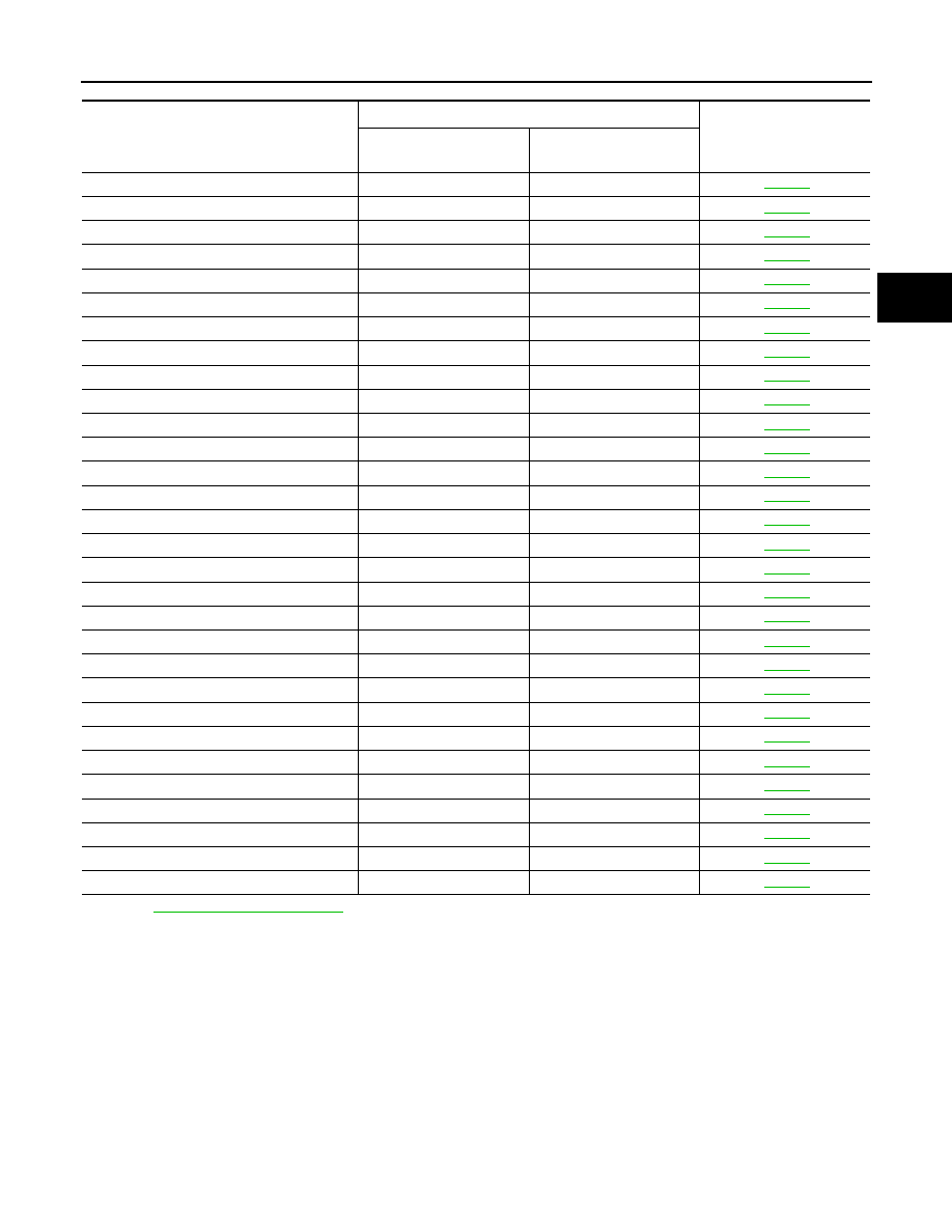
DTC Inspection Priority Chart
INFOID:0000000005250335
If some DTCs are displayed at the same time, perform inspections one by one based on the priority as per the
following list.
DTC Index
INFOID:0000000005250336
NOTE:
If some DTCs are displayed at the same time, perform inspections one by one based on the priority as per the
following list. Refer to
TM-332, "DTC Inspection Priority Chart"
Normal return condition
• TCM electronic substrate temperature: Less than 140
°
C (284
°
F)
and
• Vehicle speed: 5 km/h (3 MPH) or less
Vehicle behavior
Accelerator opening: output torque of approximately 0.5/8
Priority
Detected items (DTC)
Reference
1
U1000 CAN COMM CIRCUIT
2
P0615 STARTER RELAY
P0705 T/M RANGE SWITCH A
P0710 FLUID TEMP SENSOR A
P0717 INPUT SPEED SENSOR A
P0720 OUTPUT SPEED SENSOR
P0740 TORQUE CONVERTER
P0745 PC SOLENOID A
P0750 SHIFT SOLENOID A
P0775 PC SOLENOID B
P0795 PC SOLENOID C
P2713 PC SOLENOID D
P2722 PC SOLENOID E
P2731 PC SOLENOID F
P2807 PC SOLENOID G
3
P0729 6GR INCORRECT RATIO
P0730 INCORRECT GR RATIO
P0731 1GR INCORRECT RATIO
P0732 2GR INCORRECT RATIO
P0733 3GR INCORRECT RATIO
P0734 4GR INCORRECT RATIO
P0735 5GR INCORRECT RATIO
P0744 TORQUE CONVERTER
P0780 SHIFT
P1730 INTERLOCK
P1734 7GR INCORRECT RATIO
4
P0725 ENGINE SPEED
P1705 TP SENSOR
P1721 VEHICLE SPEED SIGNAL
P1815 M-MODE SWITCH
TCM
TM-333
< ECU DIAGNOSIS INFORMATION >
[7AT: RE7R01B (VK50VE)]
C
E
F
G
H
I
J
K
L
M
A
B
TM
N
O
P
*1: Refer to
TM-242, "Diagnosis Description"
*2: These numbers are prescribed by SAE J2012.
IGN COUNTER
IGN counter indicates the number of items that ignition switch is turned ON after DTC is detected.
• CAN malfunction
- The number is 0 when a malfunction is detected now.
- The number increases like 1
→
2
→
3...38
→
39 after returning to the normal condition whenever ignition
switch OFF
→
ON.
- The number is fixed to 39 until self-diagnosis results are erased if it is over 39.
• Except for CAN malfunction
- The number is 0 when a malfunction is detected now.
- The number increases like 1
→
2
→
3...254
→
255 after returning to the normal condition whenever ignition
switch OFF
→
ON.
- The number is fixed to 255 until self-diagnosis results are erased if it is over 255.
Items
(CONSULT-III screen terms)
DTC
*2
Reference
MIL
*1
, “ENGINE” with
CONSULT-III or GST
CONSULT-III only
“TRANSMISSION”
STARTER RELAY
—
P0615
T/M RANGE SWITCH A
P0705
P0705
FLUID TEMP SENSOR A
P0710
P0710
INPUT SPEED SENSOR A
P0717
P0717
OUTPUT SPEED SENSOR
P0720
P0720
ENGINE SPEED
—
P0725
6GR INCORRECT RATIO
P0729
P0729
INCORRECT GR RATIO
P0730
P0730
1GR INCORRECT RATIO
P0731
P0731
2GR INCORRECT RATIO
P0732
P0732
3GR INCORRECT RATIO
P0733
P0733
4GR INCORRECT RATIO
P0734
P0734
5GR INCORRECT RATIO
P0735
P0735
TORQUE CONVERTER
P0740
P0740
TORQUE CONVERTER
P0744
P0744
PC SOLENOID A
P0745
P0745
SHIFT SOLENOID A
P0750
P0750
PC SOLENOID B
P0775
P0775
SHIFT
P0780
P0780
PC SOLENOID C
P0795
P0795
TP SENSOR
—
P1705
VEHICLE SPEED SIGNAL
—
P1721
INTERLOCK
P1730
P1730
7GR INCORRECT RATIO
P1734
P1734
M-MODE SWITCH
—
P1815
PC SOLENOID D
P2713
P2713
PC SOLENOID E
P2722
P2722
PC SOLENOID F
P2731
P2731
PC SOLENOID G
P2807
P2807
CAN COMM CIRCUIT
U1000
U1000
TM-334
< SYMPTOM DIAGNOSIS >
[7AT: RE7R01B (VK50VE)]
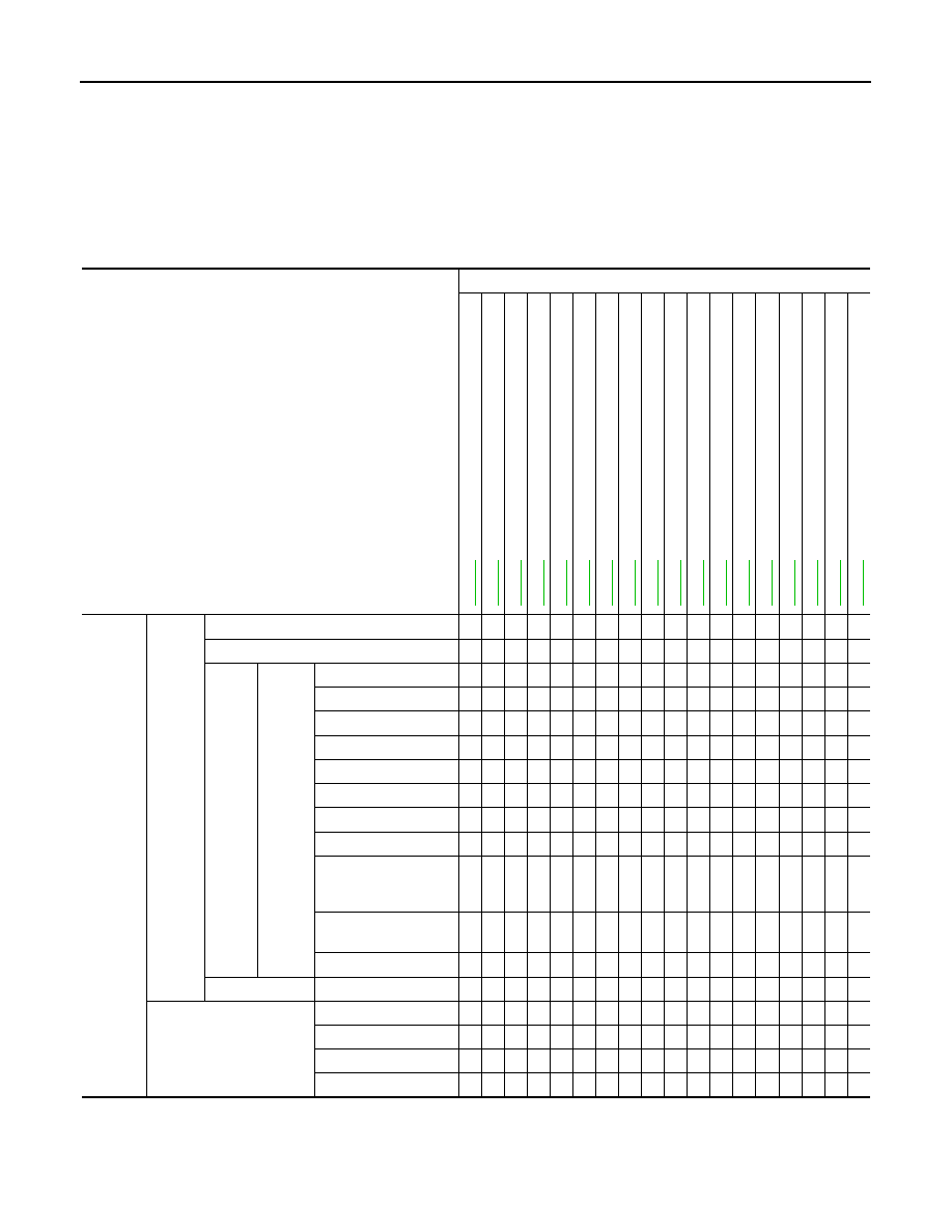
SYSTEM SYMPTOM
SYMPTOM DIAGNOSIS
SYSTEM SYMPTOM
Symptom Table
INFOID:0000000005250337
The diagnostics item numbers show the sequence for inspection. Inspect in order from item 1.
CAUTION:
If any malfunction occurs in the RE7R01A transmission, replace the A/T assembly.
Symptom
Diagnostic item
Co
ntro
l l
ink
a
g
e
Ou
tp
ut
sp
ee
d s
en
s
o
r
V
ehi
cl
e s
p
eed
s
ig
na
l
Acc
e
le
ra
to
r pe
da
l
p
o
s
it
ion
se
ns
or
En
gi
ne
sp
ee
d
sig
na
l
Inp
ut
sp
ee
d se
ns
or
A/T
f
lu
id t
e
m
p
e
rat
ure
se
ns
or
T
ran
sm
is
si
on
ran
g
e
swi
tc
h
Li
n
e
pre
ss
u
re
sol
e
no
id
va
lv
e
T
o
rq
ue
co
nv
ert
e
r s
o
le
n
o
id
v
a
lv
e
Lo
w bra
ke
s
o
le
no
id
va
lv
e
F
ron
t b
rak
e so
len
oi
d va
lv
e
Hig
h
an
d l
o
w re
ve
rse
c
lut
ch
s
o
le
no
id
va
lv
e
Inp
u
t cl
utch
so
le
no
id
va
lv
e
Dire
ct
cl
ut
ch
so
le
no
id
va
lv
e
23
46
bra
k
e
s
ol
e
no
id
va
lv
e
An
ti-i
nte
rlo
ck
s
o
le
no
id
v
a
lv
e
CAN communication
Poor
perfor-
mance
Driving
perfor-
mance
Shift point is high in “D” position.
1
2
3
Shift point is low in “D” position.
1
2
Large
shock
When
shift-
ing
gears
→
“D” position
3
6
5
5
4
2
1
2
5
→
“R” position
3
6
5
5
4
2
1
5
1GR
⇔
2GR
3
1
5
3
3
2
4
2GR
⇔
3GR
3
1
5
3
3
2
4
3GR
⇔
4GR
3
1
5
3
3
2
2
4
4GR
⇔
5GR
3
1
5
3
3
2
2
4
5GR
⇔
6GR
3
1
5
3
3
2
2
4
6GR
⇔
7GR
3
1
5
3
3
2
2
4
Downshift when accel-
erator pedal is de-
pressed
2
1
4
2
2
3
Upshift when acceler-
ator pedal is released
2
1
4
2
2
3
Lock-up
3
1
3
3
3
2
4
Judder
Lock-up
2
1
1
4
3
Strange noise
In “R” position
2
1
In “N” position
2
1
In “D” position
2
1
Engine at idle
2
1
Нет комментариевНе стесняйтесь поделиться с нами вашим ценным мнением.
Текст